A power tool that cracks after six months. A connector that strips after three assembly cycles. A medical device that fails sterilization because the soft grip separated from the housing. These are not random manufacturing failures. They are the predictable outcome of applying the wrong multi-material process to the wrong application.
Overmolding and insert molding are frequently treated as interchangeable options. They are not. Both combine multiple materials into a single integrated part. Both eliminate secondary assembly operations. But they work through completely different mechanisms, serve different design objectives, bond through different physics, and fail in different ways when misapplied.
This guide gives you a precise understanding of how each process works, what drives bond strength in each case, which material combinations are compatible, what each costs, and the specific application scenarios where one process is clearly correct and the other is clearly wrong. By the end, you will be able to look at a part drawing and know which process to specify before the tooling budget is committed.
| Quick Answer Insert molding is a single-shot process where a preformed component, most commonly a metal insert such as a brass threaded nut or stainless steel pin, is placed into a mold cavity before plastic is injected around it. The result is a metal component mechanically locked inside a plastic body. Overmolding is a two-shot process where a previously molded plastic substrate receives a second layer of a different material, usually a soft thermoplastic elastomer (TPE or TPU), injected over selected areas of its surface. Use insert molding when you need to embed metal functionality into a plastic part. Use overmolding when you need to add a soft-touch layer, seal, grip, or vibration-damping feature to an existing plastic substrate. |
How Does Insert Molding Work, and What Makes It Different?
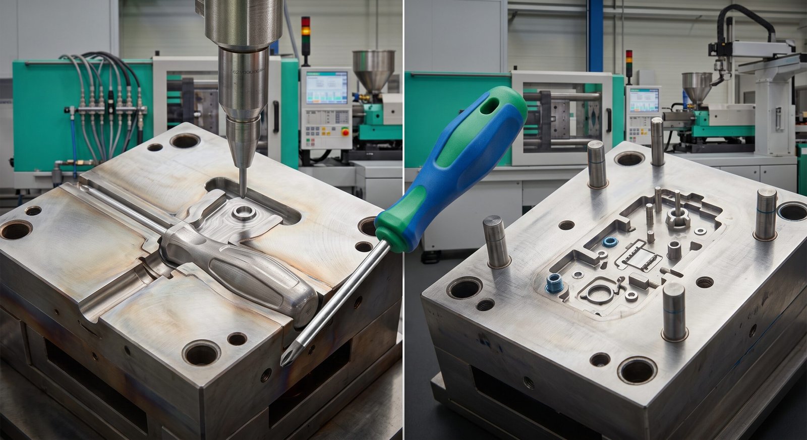
Insert molding is a single-shot injection molding process. A preformed component, the insert, is placed into the mold cavity before the mold closes. When molten thermoplastic is injected under pressure, it flows around the insert, filling the remaining cavity volume and encapsulating the insert as it cools and solidifies. The mold opens, and the finished part ejects as one integrated piece with the insert permanently bonded inside it.
The bond in insert molding is primarily mechanical rather than chemical. As the plastic shrinks during cooling, it contracts around the insert geometry, creating a compressive grip. Knurling, undercuts, holes, and flanges machined into the insert surface give the plastic material geometry to lock around, dramatically increasing pull-out resistance. A smooth-surface brass cylinder can be pulled from its plastic housing with moderate force. The same cylinder with circumferential knurling and a through-hole for plastic to flow through may require several hundred newtons of axial force to dislodge.
What Inserts Are Used and Why?
The most common insert is a brass threaded nut. Brass machines cleanly to precise thread tolerances, resists thread stripping under repeated assembly cycles, and bonds well with most thermoplastics through its surface texture. Stainless steel pins, blades, and electrical contacts are used where conductivity, wear resistance, or corrosion resistance requirements prevent plastic from serving the function. Aluminum inserts appear in weight-sensitive applications. Ceramic inserts are used in specialty electrical isolation components where dielectric properties are required.
Heat-set inserts, installed post-molding by pressing them into the plastic under heat rather than encapsulating them during molding, are a separate process category that should not be confused with insert molding. Heat-set inserts offer more flexibility in design iteration since they can be added after the main mold is built, but they provide lower pull-out strength than molded-in inserts of equivalent geometry because the compressive bond develops over a shorter engagement length.
Where Is Insert Molding Applied?
- Threaded housings: consumer electronics, power tools, and industrial enclosures where repeated screw assembly cycles would strip plastic threads use insert-molded brass nuts to provide durable metal threads in a plastic body.
- Electrical connectors: metal contact pins and blades overmolded with thermoplastic housings create single-piece connector assemblies that eliminate secondary press-fit or adhesive bonding operations.
- Automotive components: sensor housings, switch assemblies, and cable management clips use insert molding to combine metal retention features with plastic structural bodies that would fail under direct metal-to-metal fastening loads.
- Medical devices: stainless steel needles, cannulas, and contact elements molded into polymer hubs and housings create single-piece assemblies that eliminate adhesive bonding steps that add cost and introduce failure modes in sterilization environments.

How Does Overmolding Work, and What Is It Actually Solving?
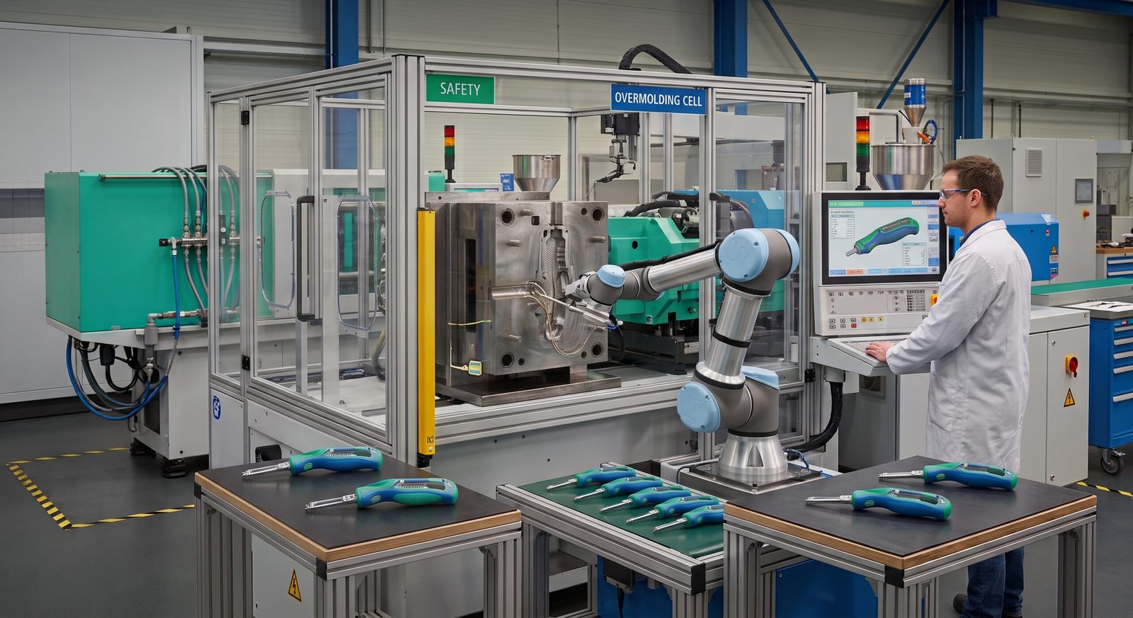
Overmolding is a two-shot process. A plastic substrate is molded first, typically in a standard injection mold. That substrate is then placed into a second mold, where a second material is injected over selected areas of its surface. As the second material cools, it bonds to the substrate surface, creating a multi-material part without adhesives, mechanical fasteners, or secondary assembly.
The bond in overmolding is primarily chemical rather than mechanical. Successful adhesion depends on three material-level factors: chemical polarity compatibility between substrate and overmold materials, surface energy of the substrate being higher than the surface tension of the molten overmold material, and thermal compatibility allowing the heat from the injected second material to create a thin inter-diffusion layer at the interface where polymer chains from both materials entangle.
Bond strength in compatible pairs is measurable and meaningful. ABS substrates with TPE overmold materials achieve peel strengths of 15 to 30 N/mm measured per ASTM D903 when process parameters are correctly set [1]. The same TPE applied to a polypropylene substrate without a compatibilizer achieves near-zero peel strength because polypropylene’s low surface energy prevents wetting and inter-diffusion. Material compatibility is not optional in overmolding. It is the entire engineering basis of the bond.
What Material Combinations Work in Overmolding?
Not all substrate and overmold material pairs bond chemically. The compatibility depends on polarity and surface energy matching. High-surface-energy substrates such as ABS and polycarbonate bond readily to polar elastomers like TPE and TPU. Low-surface-energy substrates such as polypropylene and polyethylene require specifically formulated compatibilized TPE compounds or surface treatment to achieve acceptable bond strength.
| Substrate Material | Compatible Overmold Materials | Bond Type | Typical Peel Strength | الملاحظات |
|---|---|---|---|---|
| ABS | TPE (SEBS), TPU, soft PVC | Chemical + mechanical | 15 to 30 N/mm | Most common overmolding pair. Excellent adhesion. |
| بولي كربونات (PC) | TPU, TPE (PC-compatible grade) | Chemical | 12 to 25 N/mm | Requires PC-compatible TPE grade. Standard TPE may fail. |
| ABS/PC blend | TPE، TPU | Chemical | 15 to 28 N/mm | Good adhesion. Common in consumer electronics grips. |
| Nylon (PA6/PA66) | Specialized TPE grades only | Chemical (difficult) | 5 to 15 N/mm | Standard TPE bonds poorly. Nylon surface freezes too fast. |
| البولي بروبلين (PP) | TPV, TPO (PP-compatible only) | Chemical + compatibilizer | 8 to 20 N/mm | Requires PP-specific TPE compound. Standard SEBS will not bond. |
| بيك | Specialized silicone, limited TPU | Mechanical (primarily) | Low without design features | Chemical bond difficult. Use mechanical interlocks in substrate design. |
The table above represents chemical bond performance under ideal process conditions. Contamination, moisture absorption, insufficient substrate temperature, or incorrect injection speed in the second shot can reduce bond strength by 30 to 60 percent from the values shown. Process control in overmolding is as critical as material selection.
How Do Overmolding and Insert Molding Compare Directly?
The decision between the two processes rarely comes from a preference for one technology. It comes from what the part needs to do, what the insert or overmold material is, and what failure mode the design is trying to prevent.
| Comparison Factor | إدراج القوالب | التشكيل الزائد |
|---|---|---|
| Process shots | Single shot (insert placed before molding) | Two shots (substrate first, overmold second) |
| Insert/overmold material | Metal, ceramic, or preformed plastic inserts | Thermoplastic elastomers (TPE, TPU, silicone) |
| Primary bond mechanism | Mechanical (shrinkage compressive grip) | Chemical (polymer inter-diffusion at interface) |
| Primary design objective | Add metal functionality to plastic body | Add soft-touch layer, seal, or grip to plastic body |
| Tooling requirement | Single mold with insert loading station | Two molds or one rotary two-shot mold (2K) |
| Cycle time | Slightly longer (insert placement adds 5 to 15 sec) | Longer (two full injection cycles per part) |
| Typical tooling cost | 5 to 20 percent above standard mold cost | 20 to 50 percent above substrate-only mold cost |
| Key failure mode | Insert pull-out under axial or torque load | Delamination from incompatible material pairing |
| DFM requirement | Knurling, undercuts, or through-holes on insert surface | Compatible material pair selection, substrate surface temp control |
| Primary industries | Electronics, automotive, medical, industrial | Consumer products, power tools, automotive grips, medical handles |
| Automation compatibility | High (robotic insert placement well established) | High for 2K rotary; moderate for manual transfer |
When Should You Choose Insert Molding, and When Should You Choose Overmolding?
The process selection decision follows from the functional requirement of the part, not from manufacturing familiarity or tooling cost alone. The three questions below resolve the choice for the vast majority of product development situations.
Does the Part Need to Embed Metal Functionality?
If the design requires threaded features that will undergo repeated assembly cycles, electrical contacts or conductors inside a plastic body, metal structural members for load transfer within a plastic housing, or pins, blades, or needles that must remain precisely positioned within a polymer matrix, insert molding is the correct process. No overmolding process can provide the functional properties of metal threads, electrical conductivity, or metal structural stiffness. The choice is clear.
Does the Part Need a Soft Layer, Seal, or Ergonomic Surface?
If the design requires a soft-touch grip surface to improve user comfort and reduce hand fatigue, a sealing bead or gasket integrated directly into the plastic housing without a secondary assembly step, vibration or shock damping properties in a specific zone of the part, a second color or contrasting texture for visual differentiation or brand identity, or a chemical barrier layer over a structural substrate, overmolding is the correct process. Insert molding cannot provide these functional properties because metal inserts do not deliver softness, sealing compliance, or vibration damping.
What If the Part Needs Both?
Some assemblies require both metal embedded functionality and soft exterior surfaces. A surgical instrument handle might need stainless steel inserts for cannula attachment and TPE grip surfaces for surgeon comfort and sterilization resistance. In these cases, the processes are used sequentially: insert molding first to embed the metal elements, then overmolding in a second tool to apply the TPE layer over the now-complete substrate. Elite Mold Tech designs and builds tooling for both processes and coordinates the two-stage production flow under a single BOM management system, eliminating the coordination overhead of managing multiple suppliers for a single part assembly.
What Does Each Process Cost Compared to Standard Injection Molding?
Neither insert molding nor overmolding is dramatically more expensive than standard single-material injection molding when the tooling cost is correctly allocated. The incremental costs come from specific elements in each process.
Insert Molding Cost Factors
- Insert procurement: brass threaded inserts typically cost USD 0.05 to USD 0.50 each depending on size, thread specification, and quantity. Stainless steel contact pins or blades cost USD 0.10 to USD 5.00 per piece. Insert cost is a direct per-part cost addition.
- Insert loading time: manual insert placement adds 5 to 15 seconds per cycle. Robotic placement adds 3 to 8 seconds. At a machine rate of USD 50 to USD 100 per hour, a 10-second insert placement adds USD 0.14 to USD 0.28 per part in cycle time cost.
- Mold design complexity: the mold must include precise insert locating features, pins, or nests that hold the insert in exact position during mold close and injection. This adds USD 500 to USD 3,000 to standard mold design cost depending on insert count and positioning precision.
Overmolding Cost Factors
- Second mold requirement: overmolding requires a second tool, adding USD 3,000 to USD 20,000 in tooling cost depending on complexity. Two-shot rotary molding (2K) eliminates the second mold by integrating both shots in one machine, but requires a specialized 2K injection press that costs USD 150,000 to USD 500,000 to purchase.
- Material cost: TPE and TPU overmold materials cost USD 3.00 to USD 8.00 per kilogram, similar to standard engineering resins. The overmold shot volume is typically 10 to 30 percent of total part weight, so material cost addition is modest.
- Cycle time addition: the overmold shot adds a full injection cycle per part. At a typical cycle time of 20 to 45 seconds per shot, total cycle time per finished part roughly doubles compared to single-material molding.
| Not Sure Whether Your Part Needs Overmolding or Insert Molding?Upload your STEP or IGES file to Elite Mold Tech and receive a free DFM review within 12 hours. Our engineering team will assess your geometry, material requirements, and functional objectives to recommend the correct process, provide a tooling cost estimate, and identify any material compatibility issues before a single mold is designed. All uploads are secure and covered by NDA on request.Visit elitemoldtech.com to upload your CAD file and start your process review. |
Related Elite Mold Tech Guides and Sources
Related guides: complete manufacturing process selector guide, injection mold cost breakdown, overmolding services.
Authoritative references: Society of Plastics Engineers (SPE), ASTM International plastics standards.
Get a DFM Review from Elite Mold Tech
Ready to move from drawing to part? Upload your CAD file to Elite Mold Tech and receive a DFM review within 12 hours, with tolerance, material, and cost feedback from our engineering team before you commit to tooling.
الأسئلة الشائعة
Can overmolding and insert molding be combined in the same part?
Yes, and this combination is used in several high-performance product categories where both metal functionality and soft exterior surfaces are required simultaneously. A surgical instrument handle is a clear example: stainless steel cannula attachment inserts are molded into the polymer substrate in the first operation using insert molding, and TPE grip surfaces are then applied to the exterior of that substrate in a second overmolding operation. The result is a single integrated part with embedded metal functionality, a rigid structural polymer body, and a soft sterilizable grip surface, all produced without any secondary assembly or adhesive bonding. Elite Mold Tech designs tooling sequences for both processes and manages the two-stage production flow under one program to eliminate inter-supplier coordination overhead.
What causes delamination in overmolded parts, and how is it prevented?
Delamination in overmolded parts almost always traces to one of three root causes: incompatible material pairing where the substrate and overmold materials do not share sufficient polarity or surface energy to form a chemical bond, insufficient substrate temperature at the moment of overmold injection preventing the inter-diffusion layer from forming, or contamination of the substrate surface from mold release agents, moisture absorption, or handling that blocks molecular contact at the interface. Prevention follows from each root cause in the same order: confirm chemical compatibility before tooling is built using published peel strength data per ASTM D903 for your specific material pair, control substrate temperature by minimizing the time between the first and second shot, and eliminate mold release agent use on any surface that will receive the overmold layer. Mechanical interlocking features designed into the substrate, ribs, through-holes, and undercuts that the overmold material flows into, provide a secondary retention mechanism when chemical bond strength alone is insufficient for the application load.
What is the difference between two-shot molding and overmolding?
Two-shot molding, also called 2K molding or dual-shot molding, is a specific overmolding variant that uses a single rotary injection press with two injection barrels to deliver both shots in one continuous machine cycle without removing the part from the mold between shots. The mold rotates 180 degrees after the first shot, positioning the substrate in front of the second injection barrel, which injects the overmold material directly. Two-shot molding produces shorter cycle times, higher consistency, and superior bond strength compared to manual transfer overmolding because the substrate never cools fully between shots and is never exposed to contamination during handling. The trade-off is equipment cost: a 2K rotary press costs USD 150,000 to USD 500,000 compared to two standard presses at USD 30,000 to USD 100,000 each. Two-shot molding justifies its premium at high production volumes, typically above 50,000 parts per year, where cycle time reduction and quality consistency compound into significant economic advantage.
Why do metal inserts in injection molded parts sometimes crack the surrounding plastic?
Cracking around molded-in metal inserts typically results from differential thermal expansion between the metal insert and the surrounding plastic. All metals have a coefficient of thermal expansion (CTE) that differs from all thermoplastics, and in most combinations the plastic has a significantly higher CTE than the metal. When a part cycles through temperature changes in its service environment, the plastic attempts to expand more than the metal insert. Since the insert is encapsulated and cannot move, the plastic experiences tensile hoop stress around the insert perimeter. If this stress exceeds the plastic’s tensile strength at the operating temperature, cracking occurs. Prevention involves specifying an adequate wall thickness of plastic around the insert, typically a minimum of 1.5 times the insert diameter, using toughened grades of the substrate resin that have higher elongation before fracture, and for high-temperature applications, using inserts with CTE values closer to the plastic, or pre-heating the inserts before molding to reduce the thermal shock at the plastic-metal interface.
Is insert molding possible with plastic inserts, or only metal?
Insert molding works with any preformed component that can survive the injection molding process conditions: the mold close force, the injection pressure of 10,000 to 30,000 psi, the melt temperature of the injected resin, and the cooling cycle. Metal is the most common insert material because it easily survives all of these conditions and provides the functional properties most commonly needed in insert molding applications. Plastic inserts are used when the second material provides a property the first molded plastic cannot, such as a transparent window of polycarbonate insert-molded into an opaque housing, or a high-temperature PEEK insert in a lower-cost polyamide body. Ceramic inserts are used in electrical isolation applications. The constraint is that the insert must have greater dimensional stability and resistance to deformation under injection conditions than the plastic being injected around it, otherwise the insert distorts during the molding process and the finished part fails dimensional inspection.
How do you specify the correct brass insert for an injection molded threaded feature?
Brass insert selection for injection molded threaded features involves four parameters: thread size and type (metric or unified, coarse or fine pitch), insert length relative to wall thickness (insert length should be at least 1.5 times the insert diameter to provide adequate pull-out resistance), installation method (molded-in during injection vs. heat-set post-molding vs. ultrasonic installation), and knurling pattern on the insert outer diameter. For molded-in inserts, diamond knurling on the outer diameter provides the highest pull-out and torque-out resistance because it gives the encapsulating plastic maximum mechanical interlock geometry as it shrinks around the insert. The insert outer diameter determines the minimum boss diameter in the plastic part: boss diameter should be at least 2.0 to 2.5 times the insert outer diameter to prevent hoop stress cracking during cooling. Standard brass inserts from manufacturers such as Heli-Coil, Penn Engineering, and Böllhoff are available with documented pull-out force specifications, allowing the design to be validated against the fastener torque requirement before production tooling is committed.
About the Author:
Alex Morgan specializes in technical content for precision manufacturing, with a focus on CNC machining, injection molding, die casting, 3D printing, sheet metal fabrication, and custom mold manufacturing. With more than a decade of experience in B2B manufacturing content and SEO, he creates technically accurate content designed for engineers, product developers, procurement teams, and manufacturing decision-makers. His work helps global manufacturers clearly communicate complex production capabilities, material options, tolerances, tooling processes, and quality standards to customers across the US, Europe, and Asia-Pacific. He writes for manufacturing companies where technical expertise, precision, and reliability matter.