هل سبق لك أن نظرت من قبل إلى رسم ورصدت علامة "⊥" الصغيرة من أعلى إلى أسفل بجانب أحد الأبعاد؟ ترمز هذه العلامة إلى التعامد GD&Tوهي قاعدة هندسية تنص على التقاء سطحين بزاوية قائمة مثالية. إذا انحرفت هذه الزاوية، ولو بمقدار شعرة واحدة، فقد تنحشر الأجزاء، وقد تنحرف التروس، وقد يتأرجح المشروع بأكمله. وهذا هو سبب وجودك هنا - للتأكد من أن الأجزاء الخاصة بك تبقى مربعة وتبقى راحة بالك سليمة.
إجابة سريعة للقارئ المشغول: التعامد GD&T يتحكم في مدى ميل السطح أو المحور أو الخط المركزي بعيدًا عن زاوية 90 درجة بالنسبة إلى مسند مختار. التفاوت المسموح به عبارة عن أسطوانة أو مربع نحيف ثلاثي الأبعاد؛ احتفظ بكل نقطة من الميزة داخل تلك المنطقة وستجتاز الفحص.
سنقوم في هذا الدليل بتفكيك الرمز، وإطار التحكم، وأمثلة حقيقية في المتجر، وطرق القياس، والأخطاء الشائعة، ورؤية واضحة لكيفية اختلاف العمودية عن نظيرتها الزاوية. اربط حزام الأمان من أجل كلمات بسيطة وتورية سيئة والكثير من النصائح العملية.
شرح التعامد المتعامد | كيف يكون التعامد القياس
قد يبدو التعامد وكأنه كلمة طويلة في الفم، ولكنه في الحقيقة وعد بأن شيئين يقفان متعامدين بشكل متعامد وصحيح، تمامًا مثل زاوية كتابك الهزلي المفضل. في المخطط، يظهر الرمز ⊥ في إطار التحكم في الميزة مع قيمة الحجم. تقول هذه القيمة: "عزيزي الميكانيكي، لديك هذا القدر من المساحة للمناورة لتبقى قريبًا من 90 درجة". إذا ابتعدت الميزة عن الحد المسموح به، فلن يكون الجزء مناسبًا. هذه الملاحظة الصغيرة أرخص من إلغاء الأجزاء لاحقًا، لذا فإن فهمها يحافظ على سلامة كل من المحافظ والجداول الزمنية. أفضل ما في الأمر أن الفكرة تصلح للجدران والدبابيس وحتى المحاور غير المرئية.
فهم إطار التحكم في الميزة
عندما ترى مستطيل محشو بالرموز، فهذا هو إطار التحكم في الميزة. تُظهر الفتحة الأولى الرمز ⊥، الذي يخبرنا بالقاعدة. بعد ذلك يأتي رقم مثل 0.05 مم، و تفاوت العمودية التي تحدد مدى اتساع المنطقة. بعد ذلك، يشير حرف أو أكثر إلى أسطح المسند التي تستخدمها كمرجع. فكّر في الإطار كعنوان على عبوة: فبدونه لا تملك معدات الفحص الخاصة بك أي فكرة عن مكان التصويب. اقرأه مرة واحدة ويصبح الإعداد بسيطًا وسريعًا وقابلًا للتكرار. كل فتحة مهمة.
دور الداتوم
تخيل أنك تبني منزل شجرة: تختار لوحًا مستقيمًا واحدًا كخط أساس قبل تثبيت الألواح الأخرى عليه. في GD&T، يكون هذا اللوح المستقيم هو المسند. المسند في الشرح المتعامد يحدد الاتجاه بحيث تعرف بالضبط المستوى أو المحور الذي ترتبط به قاعدة الـ90 درجة. قد يكون المسند وجهًا مسطحًا أو خطًا مركزيًا للفتحة أو حتى مستوى افتراضي في المنتصف. بمجرد التثبيت، يقوم المفتش بإسناد الجزء على أجهزة محاكاة المسند، ويصبح اختبار العمودية لعبة عادلة بدلاً من التخمين. لا مسند، لا ثقة، لا عملاء سعداء.
مثال من العالم الحقيقي
لنفترض أنك تعطي خدمات التصنيع باستخدام الحاسب الآلي باستخدام الحاسب الآلي إلى كتيفة تركيب. يجب أن يكون هناك فتحتا مسمار في وضع مستقيم من القاعدة. يمكنك إضافة الرمز ⊥ برمز 0.02 مم تفاوت العمودية بالرجوع إلى المسند A، القاعدة. أثناء الفحص، يقوم ذراع السبر بمسح الثقب وبناء محور أفضل ملاءمة. إذا كان هذا المحور يستقر بالكامل داخل أسطوانة قطرها 0.02 مم يكون خط مركزها عموديًا تمامًا على المسند A، فإن الثقب يمر. في وقت لاحق تنزلق القوس على مسامير التزاوج دون قتال. تؤدي الرسومات الجيدة إلى تثبيت سلس.
تنشيط الأبعاد الهندسية والمقايسة الهندسية
قبل التعمق أكثر، من المفيد الإجابة عن السؤال البسيط الذي تثيره العديد من المطبوعات: ما هو التعامد? GD&T هي لغة من الرموز التي تتحكم في حجم السمات وشكلها والعلاقة بينها. التعامد GD&T العمودي هي كلمة واحدة فقط في تلك اللغة، لكنها تتحدث بصوت عالٍ لأن الزوايا القائمة تظهر في كل مكان - من إطارات الهواتف الذكية إلى شاحنات ألواح التزلج. من خلال تعريف الاتجاه، فهي تتحد مع التسطيح والتوازي و رمز التربيع للحفاظ على اتساق التصميمات.
يمكن للملاحظات التقليدية زائد ناقص التقليدية أن تحدد الحجم، لكنها تظل صامتة بشأن المكان الذي يجب أن يشير إليه السطح. يتسبب هذا الصمت في تجميعات متذبذبة. تملأ GD&T الفجوة بقواعد موضوعية خالية من الحجج. يُظهر تصفح سريع للمعيار Y14.5 ما لا يقل عن ثلاثة وعشرين رمزًا؛ ويمكن القول إن العلامة ⊥ هي الأسهل في التصور. أتقنها وستشعر أن المشاريع لا تحتاج إلى جهد.
التعمق أكثر في إطار التحكم في الميزة
فكّر في إطار التحكم في الميزة كرسالة نصية قصيرة تحمل معنى كبير حول التعامد GD&T. يوضّح الرمز الأول القاعدة التي نستخدمها - وهي هنا ⊥. القيمة التالية، وهي تفاوت العموديةتُسمّى المنطقة المسموح بها. بعد ذلك تأتي المسندات بترتيب الأولوية. اخلط الترتيب وستتبع ذلك فوضى الفحص. ينظر الميكانيكيون مباشرةً إلى هذا الإطار عند تعيين إزاحات الأدوات، بينما يعكسه المفتشون في برامج CMM الخاصة بهم. قد يتسبب نسيان أحد المسندات في مطاردة السطح الخطأ. ونظرًا لأن إطارات GD&T توجد دائمًا بجوار البُعد الذي تتحكم فيه، فلن تحتاج أبدًا إلى قلب الصفحات.
هل تريد ملاءمة أكثر إحكاماً؟ قلص التفاوت المسموح به. هل تحتاج إلى تكلفة أقل؟ قم بتوسيعه قليلاً. تذكر، الإطار هو وعد بين المصمم والمنشئ. عندما يسأل شخص ما عن الشرح المتعامدفقط أشر إلى ذلك المستطيل المرتب - فهو يحمل القصة بأكملها.
فك شفرة منطقة التسامح العمودي
سحر تفاوت العمودية يكمن في قفصه غير المرئي الذي صنعه التعامد GD&T. بالنسبة للسطح، يكون القفص عبارة عن زوج من المستويات المتوازية التي تقع على مسند بزاوية 90 درجة تمامًا. بالنسبة للمحور، تخيل أسطوانة طويلة نحيفة. يجب أن تستقر الميزة الخاصة بك بالكامل داخل القفص - لا غش في الزوايا. يبدو ذلك صارمًا، لكنه يوفر حرية أكبر من التفاوتات الخطية القديمة لأن السطح بأكمله يمكن أن يطفو طالما بقيت كل نقطة داخله. يطلق عليها محترفو المقاييس اسم "المساحة الإضافية" عندما يسمح التسامح المعتمد على الحجم بالتجول أكثر في MMC.
إذا كان الشرح المتعامد إذا قرأت ⊥ ⊥ | 0.1 | A | B، فستعرف على الفور أن القفص بعرض 0.1 مم ومثبت على المسندين A و B. ولأن GD&T يبني مناطق تفاوت ثلاثية الأبعاد، فإنه يجيب على اللغز التقليدي ما هو التعامد في ظل ظروف تصنيع حقيقية - وليس على شبكة رياضية مثالية. على عكس رمز التربيع، فإنه يتعلق بالمسندات، مما يجعله أكثر تنوعًا.
المقارنة بين رمز التربيع ورمز التعامد
غالبًا ما يستبدل الأشخاص رمز التربيع مع ⊥، لكن المبادلة خطيرة. ينص الرمز الذي يشبه المربع، الموجود في رسومات ISO، ببساطة على أن السطحين يجب أن يكونا 90 درجة بالنسبة لبعضهما البعض بدون تحديد نقطة مرجعية. وعلى النقيض من ذلك، التعامد GD&T تربط القاعدة دائمًا بنقطة مرجعية، مما يجعل عملية الفحص قابلة للتكرار. اسأل عن «ما هو التعامد "من منظور معايير ISO؟" وستجد شرحًا لكلا الرمزين، لكن قوة تأثيرهما تختلف. فاستخدام الرمز الخاطئ قد يتيح للمصنع حرية اختيار أي سطح مرجعي يفضلونه. وقد تبدو هذه الحرية أمرًا جيدًا إلى أن تتعذر ملاءمة قطع غيار من موردين مختلفين.
نصيحة سريعة: عندما يحتاج تصميمك إلى خط أساس ثابت، فاختِر التوازي مع العمودي بدلاً من التوازي مع الأفقية؛ فالحرف المرجعي يُلزم الجميع بالالتزام بنفس القواعد.
أخطاء يجب تجنبها في توضيحات العموديّة
حتى المصممين المخضرمين يقعون في فخ الشرح المتعامد لأن التعامد GD&T تحتوي على تفاصيل دقيقة. والخطأ الشائع هو إغفال أحد المعلمات، مما يحول عملية التحكم الدقيق في الاتجاه إلى لعبة تخمين. ومن الفخاخ الأخرى تراص تفاوت العمودية على سطح سيخضع لللحام لاحقًا — فالحرارة قد تشوه الزوايا القائمة تمامًا مثل جبن البيتزا الساخن. اعتمد على الواقعية، لا على التمني.
تحذيرات: التفاوتات الدقيقة تكلف مالاً؛ لذا لا تحددها إلا عندما تتطلب الوظيفة ذلك.
المشكلة الثالثة هي الخلط بين الوحدات — مثل كتابة 0.02 بوصة بينما المقصود هو المليمترات. ستقوم أدوات الفحص بوضع علامة على كل قطعة. أخيرًا، يقوم بعض الأشخاص بإخفاء الإطار في زاوية من الورقة. احتفظ به بالقرب من البعد الذي ينظمه حتى يتمكن عمال الآلات من رؤيته بنظرة سريعة. عند الشك، راجع أمثلة Y14.5؛ فهي توضح الطريقة الصحيحة الشرح المتعامد بصورة واضحة لا لبس فيها. قبل الإصدار، قم بإجراء مراجعة أقران تركز فقط على كل الشرح المتعامد وستكتشف الأخطاء المطبعية الخفية.
التأثير الوظيفي على التجميع والأداء
تخيل علبة تروس تكون فيها مقاعد المحامل غير متعامدة مع سطح العلبة. فحتى مع وجود أبعاد مثالية، يؤدي أي انحراف طفيف إلى زيادة الاحتكاك والضوضاء والتلف المبكر. وهذا العيب هو بالضبط ما التعامد GD&T يهدف إلى وقف. من خلال وضع تفاوت العمودية، فأنت تحافظ على استقامة الأعمدة، ومحاذاة التروس، وتوزيع الحمل بالتساوي على الموانع.
الحقائق: إن انحرافًا بمقدار 0.05 ملم على لوح طوله 100 ملم يعادل حوالي 0.03 درجة من الميل — وهو ما يكفي لإصدار صرير!
يحب المُجمِّعون القطع التي تستقر في مكانها دون الحاجة إلى مطارق مطاطية. ويحب العملاء المنتجات التي تعمل دون ارتفاع في درجة الحرارة وبهدوء. اجمع المزايا: نفايات أقل، عمليات تجميع أسرع، مطالبات ضمان أقل. تلك العلامة ⊥ الواحدة هي بوليصة تأمين صغيرة ذات عائد ضخم. إذا شككت يومًا في قيمتها، فتحدث إلى فني اضطر إلى تسوية سطح تلامس معوج لمدة ثماني ساعات متواصلة. كل هذه المزايا تنبع من الشرح المتعامد على الرسم. كل يوم.
أدوات القياس: كيفية فحص العموديّة وفقًا لمعايير GD&T كالمحترفين
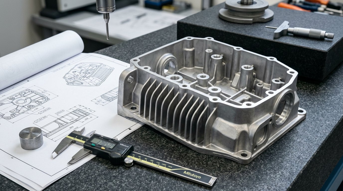
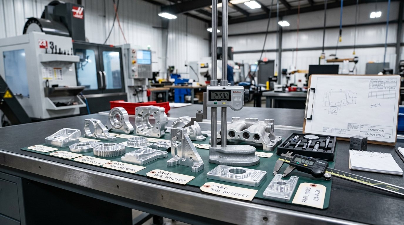
قبل قطع الرقائق، عليك أن تضع خطة لـ كيفية التحقق من التعامد وأثبت التعامد GD&T ملاحظة. في المرآب، يكفي استخدام مربع ميكانيكي بسيط. أما في المختبر، فقد تحتاج إلى استخدام آلة قياس الإحداثيات (CMM). وبغض النظر عن الأداة المستخدمة، فإن الهدف لا يتغير أبدًا: التأكد من بقاء نقاط الميزة ضمن النطاق المسموح به. فيما يلي ورقة مرجعية موجزة يمكنك لصقها على صندوق أدواتك.
| الأداة | الدقة النموذجية | متى تستخدم |
|---|---|---|
| مربع الميكانيكي | ±0.02 مم | الفحص العشوائي للقطعة الأولى |
| مقياس مقياس على لوح قياس | ±0.01 ملم | فحص الدفعات الصغيرة |
| منقلة رقمية | ±0.05 درجة | الألواح الكبيرة والقطع الملحومة |
| CMM | ±0.005 ملم | قطع غيار وتقارير عالية الدقة |
| مقارن بصري | ±0.015 ملم | ملامح رفيعة أو دقيقة |
الآن بعد أن اطلعت على الخيارات المتاحة، اختر الأداة الأرخص التي لا تزال تلبي احتياجاتك. إذا سأل مهندسو الجودة كيفية التحقق من التعامد عند فحص ثقب مغلق، أظهر لهم حيلة مؤشر الدبوس الملائم. حافظ على نظافة المقياس، واضبطه على الصفر عند نقطة الإحداثيات، ثم مرر المسبار ببطء على السمة. لا تضغط على المسبار أبدًا.
نصيحة سريعة: سجل أعلى وأدنى قراءة واطرحهما؛ والفرق هو معدل النحافة لديك.
بالنسبة للخطوط الآلية، قم ببرمجة جهاز قياس التنسيق (CMM) بحيث يصدر صوتًا بسيطًا للإشارة إلى النجاح أو الفشل. إذا نسي أحدهم كيفية التحقق من التعامد، علق هذا المخطط بجانب الآلة.
العموديّة في التصنيع باستخدام الحاسب الآلي والطباعة ثلاثية الأبعاد
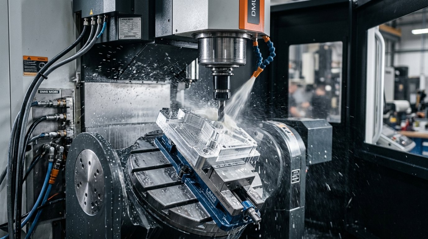
قطع المعادن باستخدام آلات الطحن بالتحكم الرقمي غالبًا ما يبدو الأمر تلقائيًا، لكن المغزل قد ينحرف مع ذلك. وللحفاظ على التعامد GD&T يجب عليك ضبط محاذاة رأس الماكينة، وقياس نقاط الإسناد، ومراقبة انحراف الأداة. فعندما تزداد عمق التدرجات، يؤدي الانحراف إلى ثني القاطع، لذا يجب استخدام ربطة أكثر مرونة تفاوت العمودية أو استبدلها بثقابات ذات طرف صلب.
في الطباعة ثلاثية الأبعاد، تنعكس المشكلة. تتراكم الطبقات فوق بعضها البعض، ويؤدي أي انحراف طفيف في محاذاة المنصة إلى ميل الأجزاء بأكملها. بالنسبة للأسطح الوظيفية، قم بتوجيه النموذج بحيث تُطبع السطح الحساس مقابل لوح البناء — فهو عادةً المرجع الأكثر استواءً. بعد الطباعة، يمكن استعادة الزاوية الصحيحة من خلال قطع خفيف.
تستفيد كلتا العمليتين من أجهزة الفحص أثناء العملية التي تتحقق من الميزات في منتصف العملية وتُشير إلى أي انحرافات في وقت مبكر. إن اتخاذ الإجراءات الوقائية يستغرق دقائق معدودة، لكنه يوفر ساعات من الوقت. احرص دائمًا على تحديث الشرح المتعامد في حالة تغير خطة العملية في منتصف المشروع.
ما الفرق بين الزاوية والعموديّة؟ توضيح الأمور
يسأل المصممون أحيانًا، ما الفرق بين الزاوية والعموديّة؟ الإجابة المختصرة هي: الزاوية مقابل الزاوية القائمة. تُحدد الزاوية أي زاوية — 30 درجة، 45 درجة، 73 درجة — بالنسبة إلى نقطة مرجعية. التعامد GD&T العمودي هو شكل محدد من الزوايا التي تبلغ 90 درجة.
لماذا لا نستخدم رمزًا واحدًا لكليهما؟ الدقة. عندما تكتب ما الفرق بين الزاوية والعموديّة؟ على السبورة البيضاء، يمكنك التأكيد على أن التعامد يجلب دائمًا ميزة إضافية: تفاوت إضافي عند الحد الأقصى للقياس (MMC) عندما يتعلق الأمر بسمات الحجم.
تمييز آخر: منطقة التفاوت المسموح بها للانحراف الزاوي هي زوج من المستويات يتم تدويرهما إلى الزاوية المطلوبة. أما منطقة التفاوت المسموح بها للعموديّة، فتقتصر على الزوايا القائمة فقط. لذا، في المرة القادمة التي يرسل فيها أحدهم رسالة إلكترونية تقول: «ما الفرق بين الزاوية والعموديّة؟"ستكون لديك الملخصات جاهزة — نفس العائلة النحوية، لكن أحد الأبناء عالق إلى الأبد عند زاوية تسعين درجة. وهذا الوضوح يسرع عملية الاستشهاد والتحقق من الجودة في موقع العمل."
الخاتمة
تتلخص "العموديّة" في GD&T في مهمة واحدة: الحفاظ على استقامة الأجزاء بحيث تتراصف جميعها، وتتحرك بسلاسة، وتدوم لفترة أطول. لقد استعرضنا رمزها وإطار التحكم ومنطقة التفاوت وحيل القياس والطرق التي توفر بها المال في كل مرحلة. ضع علامة ⊥ في الأماكن الصحيحة ونم بهدوء مع العلم أن الأسطح المائلة لن تؤثر سلبًا على الإنتاج. تذكر أن الرسومات هي بمثابة مصافحة بين التصميم والتصنيع؛ واضحة التعامد GD&T يحافظ على مصافحة قوية.
سواء كنت تقوم بربط مسمار واحد أو تطلق عملية إنتاج بمليون وحدة، فإن القاعدة نفسها تنطبق: حدد نقاط الإسناد بحكمة، واختر أرقامًا واقعية، وتحقق من الدقة باستخدام الأدوات المناسبة. إذا فعلت ذلك، فلن تكون «العموديّة» مجرد مفهوم هندسي مخيف، بل ستصبح وعدًا بسيطًا يمكنك قياسه.
الأسئلة الشائعة
ما الفرق بين العموديّة والتوازي؟
التوازي هو بقاء خطين أو سطحين جنبًا إلى جنب على مسافة ثابتة بينهما، بينما التعامد هو تثبيتهما بزاوية قائمة.
هل يمكن تطبيق مبدأ التعامد على نمط الثقوب؟
نعم. ضع الرمز بجانب ملاحظة النموذج وأشر إلى نقطة مرجعية؛ حيث سيقوم المفتشون باختبار المحور المتوسط لكل ثقب.
هل تتطلب العموديّة وجود نقطة مرجعية؟
في الغالب. فبدون نقطة مرجعية، لا يمكن تحديد المستوى المرجعي بزاوية 90 درجة، وبالتالي تفقد عملية التحكم معناها.
كيف يتم قياس العموديّة في موقع العمل بدون جهاز قياس منسقي (CMM)؟
استخدم لوحًا مسطحًا ومقياسًا قرصيًا أو مربعًا معايرًا لإجراء فحوصات سريعة.
ماذا يحدث إذا تجاوزت حدود التفاوت المسموح به في العموديّة؟
هذه القطعة لا تتوافق مع المواصفات وقد تتسبب في انحشار أو تسرب أو تآكل إضافي عند تركيبها.