The smallest safe sheet metal bend radius depends on material and temper: about 0.5T to 1T for cold-rolled steel and 5052-H32 aluminum, around 1T for annealed 304 stainless, and 2T to 6T for 6061-T6. The K-factor, usually between 0.33 and 0.50, locates the neutral axis so you can calculate flat blank length before cutting.
What Bend Radius and K-Factor Mean
The inside bend radius (R) is the radius on the inside of the bend, and the outside radius equals R plus material thickness (T).
When sheet bends, the outside stretches while the inside compresses. Somewhere between them sits the neutral axis, the one layer that keeps its original length through the bend. It does not stay at mid-thickness; it shifts toward the inside of the bend.
The K-factor describes that shift:
K = t ÷ T
where t is the distance from the inside surface to the neutral axis. A K-factor of 0.50 means the neutral axis sits at mid-thickness. Real bends usually fall between 0.33 and 0.50. The K-factor matters because the neutral axis length is the length you cut, so it drives every flat pattern.
Minimum Sheet Metal Bend Radius by Material
Bending tighter than the minimum bend radius cracks the outside surface. The ranges below are common guidance for bends across the rolling direction.
| Material and temper | Typical minimum inside radius | Примечания |
| Cold-rolled low-carbon steel | 0.5T–1T | Very formable in thin gauges |
| 304 / 316 stainless, annealed | About 1T, up to 2T in thicker gauges | Work hardens; more springback |
| 5052-H32 aluminum | About 1T, 0.5T in thin gauges | The easy-bending aluminum |
| 6061-T6 aluminum | 2T–3T thin, up to 4T–6T heavier | Low ductility; cracks easily |
| Annealed copper and brass | Tight, often below 1T | Soft; mark easily |
Two factors shift these numbers. Grain direction matters: bending parallel to the rolling direction cracks more easily, so rotate the blank on the sheet when a bend is critical. Temper matters too: 6061 bent in the O or T4 temper and aged afterward can take far tighter radii than T6. Mill specifications such as ASTM B209 set bend requirements for aluminum sheet by alloy and temper, and are the reference to check for critical parts.
Our advice is simple. If a design needs tight bends in aluminum, use 5052-H32 rather than fighting 6061-T6.
K-Factor Chart by Material and R/T Ratio
K-factor depends mostly on the ratio of inside radius to thickness (R/T). Tight bends pull the neutral axis further inward.
| Материал | R/T below 1 | R/T 1 to 3 | R/T above 3 |
| Алюминий | 0.33 | 0.40 | 0.50 |
| Мягкая сталь | 0.38–0.42 | 0.42–0.46 | 0.50 |
| Нержавеющая сталь | 0.40–0.44 | 0.44–0.48 | 0.50 |
Bending method shifts it as well. Protolabs cites about 0.33 for an air bend and 0.42 for a bottom bend when R is below T. Treat every chart value as a starting point, then confirm with a test bend on your actual material and tooling.
How to Calculate Bend Allowance and Bend Deduction
Follow these steps for a single bend:
- Collect the inputs: thickness T, inside radius R, bend angle A in degrees, and K-factor K.
- Bend allowance (BA), the arc length of the neutral axis: BA = (π ÷ 180) × A × (R + K × T)
- Outside setback (OSSB): OSSB = tan(A ÷ 2) × (R + T)
- Bend deduction (BD): BD = 2 × OSSB − BA
- Flat length from outside flange dimensions: flat = flange 1 + flange 2 − BD
Worked example. A 2 mm cold-rolled steel bracket has a 90° bend, a 2 mm inside radius and flanges of 50 mm and 30 mm measured to the outside. Using K = 0.42:
- BA = 1.5708 × (2 + 0.84) = 4.461 mm
- OSSB = tan 45° × (2 + 2) = 4.000 mm
- BD = 8.000 − 4.461 = 3.539 mm
- Flat length = 50 + 30 − 3.539 = 76.46 mm
Bend allowance adds to the inside flange lengths, while bend deduction subtracts from the outside dimensions. They describe the same geometry from opposite sides, and mixing them up is one of the most common flat-pattern errors.
Finding Your Real K-Factor From a Test Bend
Charts get you close; a test bend gets you exact. Cut a strip of known length, bend it on the production tooling, and measure both outside flanges.
Example: a 2 mm strip cut to 80.00 mm is bent to 90° with a 2 mm inside radius. The outside flanges measure 50.0 mm and 33.6 mm.
- Measured BD = 50.0 + 33.6 − 80.0 = 3.6 mm
- BA = 2 × OSSB − BD = 8.0 − 3.6 = 4.4 mm
- K = (BA ÷ (π × A ÷ 180) − R) ÷ T = (4.4 ÷ 1.5708 − 2) ÷ 2 = 0.40
Store that value in your CAD sheet metal settings for that material, thickness and tooling combination. Busy shops keep a bend deduction table instead. Same idea.
Springback and How Shops Compensate
Metal springs back slightly after the punch lifts, so a bend formed at exactly 90° opens up past it. The effect grows with material strength and with larger radii. Stainless and high-strength steels spring back more than mild steel, and 5052 aluminum sits in between.
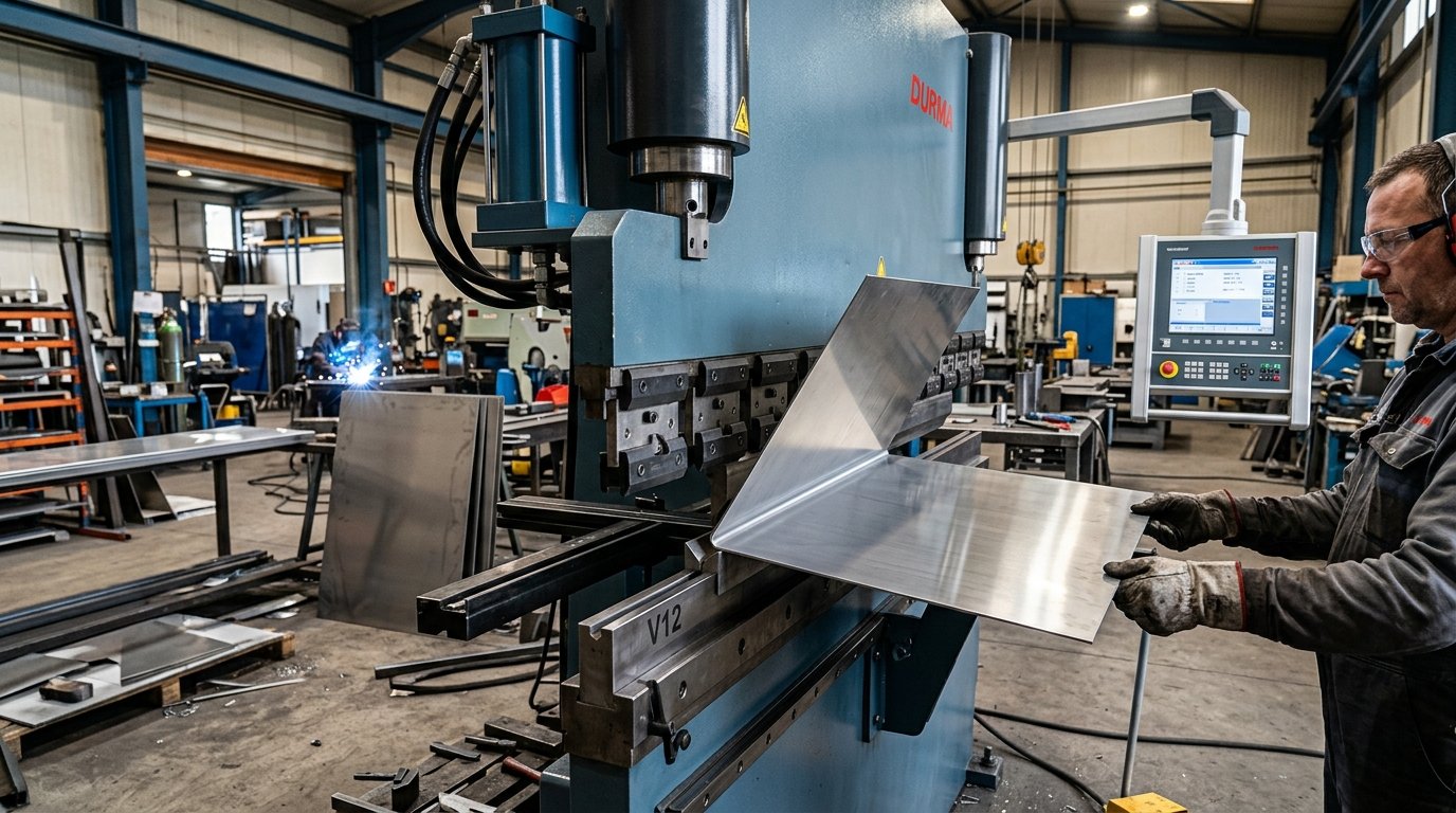
Press brake operators compensate by overbending, adjusting the stroke depth, or bottoming the bend. Modern CNC brakes with angle measurement correct on the fly. For design, the point is simple: an unusually large radius in a springy material makes the final angle harder to hold, so do not specify a big radius just for looks.
Common K-Factor Mistakes
- Using one CAD default for every material and thickness
- Taking a K-factor chart value as final without a test bend
- Mixing inside and outside dimensions in the same flat calculation
- Ignoring that a new press brake die can change the formed radius
- Sending a flat pattern built with your K-factor, then letting the shop apply its own deduction on top
Air Bending, Bottoming and Coining
The bending method changes both the radius you get and the K-factor you should use.
- Air bending presses the sheet into a V-die without bottoming. The inside radius is set mainly by the die opening, not the punch tip, so a wider V gives a larger radius. It is flexible and needs the least force, but springback varies with material lots.
- Bottoming pushes the sheet against the die walls. Angles are more consistent and springback is lower.
- Coining squeezes the bend under very high force so the punch tip sets the radius. It holds angles tightly but needs far more tonnage and wears tooling faster.
Most press brake work today is air bending. If your drawing calls a radius that only coining can produce, expect a higher price or a request to change it.
Tolerances Across Multiple Bends
Each bend adds its own error, and those errors stack. A part with four bends between two holes can drift far more than a single bend suggests.
Компания «Elite Mold Tech» производство листового металла works to ISO 2768-1 medium class (ISO 2768-mK) by default, holding about ±0.010 in on laser-cut features and ±0.020 in on bent dimensions. Tighter limits on selected features can be discussed at quote stage.
Practical ways to limit the stack:
- Dimension critical features from one datum, not bend to bend
- Keep holes that must align on the same flange where possible
- Place holes at least the bend radius plus a few thicknesses away from a bend, or they distort
- Add bend relief where a bend meets an edge
What to Send Your Fabricator
A clean request avoids flat-pattern disputes:
- A 3D model with the intended inside radius, plus a 2D drawing with tolerances
- Material grade and temper, since 5052-H32 and 6061-T6 bend very differently
- Whether dimensions are inside or outside, and which flange is the datum
- Your flat pattern only if you want it built exactly as drawn; otherwise let the shop apply its own bend deduction table
Our DFM engineers check radii, reliefs and hole spacing before quoting. For high volumes, the same part can move from the press brake to a die, as explained in our metal stamping guide and our comparison of progressive, transfer and compound dies.
Часто задаваемые вопросы
What is a good K-factor for sheet metal?
Most bends fall between 0.33 and 0.50. Tight bends, with an inside radius smaller than the thickness, sit near 0.33 to 0.42 depending on material and method. Larger radii move toward 0.50. Start with a chart value, then confirm with a test bend on your material and tooling before production.
Is K-factor always 0.33?
No. A value of 0.33 is common for tight air bends, especially in aluminum, and many CAD systems use it as a default. Mild steel and stainless often run higher, around 0.40 to 0.48 in common press brake work. Using the wrong value produces blanks that are consistently too long or too short.
What is the minimum bend radius for 6061-T6?
Guidance generally puts it at about 2T to 3T in thin gauges and up to 4T to 6T in heavier sheet, because the T6 temper has low ductility. For tighter bends, form 6061 in a softer temper and age it afterward, or switch to 5052-H32, which bends to about 1T.
Should the bend radius equal the material thickness?
For many steels and 5052 aluminum, an inside radius equal to thickness is a safe, economical default that standard tooling handles well. It is not universal. 6061-T6 needs more, while soft copper can go tighter. Matching the radius to available press brake tooling also keeps cost down.
What is the difference between bend allowance and bend deduction?
Bend allowance is the length of the neutral axis through the bend, added to the inside flange lengths. Bend deduction is the amount subtracted from the sum of the outside flange lengths. Both give the same flat length; they simply start from different dimensions, so use the one that matches your drawing.
Getting the Sheet Metal Bend Radius Right
A good sheet metal bend radius respects the material’s limits, matches standard tooling, and is paired with a K-factor proven on the shop floor. Pick the alloy for the bend, calculate with real K values, and dimension from datums to control stack-up. Elite Mold Tech builds prototypes by press brake and moves repeat parts into precision stamping when volumes justify a die.