Оглавление

SLA vs SLS vs FDM 3d Printing

SLA vs SLS vs FDM: Which 3D Printing Process Is Right for Your Prototype?

An aerospace engineer orders SLA prototypes for a bracket that needs to survive vibration testing. The parts arrive with excellent surface finish and tight dimensional accuracy. They shatter in the first load cycle. The resin could not handle the impact. Three weeks and USD 800 later, the same bracket in SLS nylon passes the test on the first run.

A product design team orders SLS nylon parts for a presentation model that needs to show a client exactly what the final product will look like. The parts arrive strong, functional, and dimensionally accurate. They have a grainy surface texture that looks nothing like an injection-molded part. The client asks whether the production version will look the same.

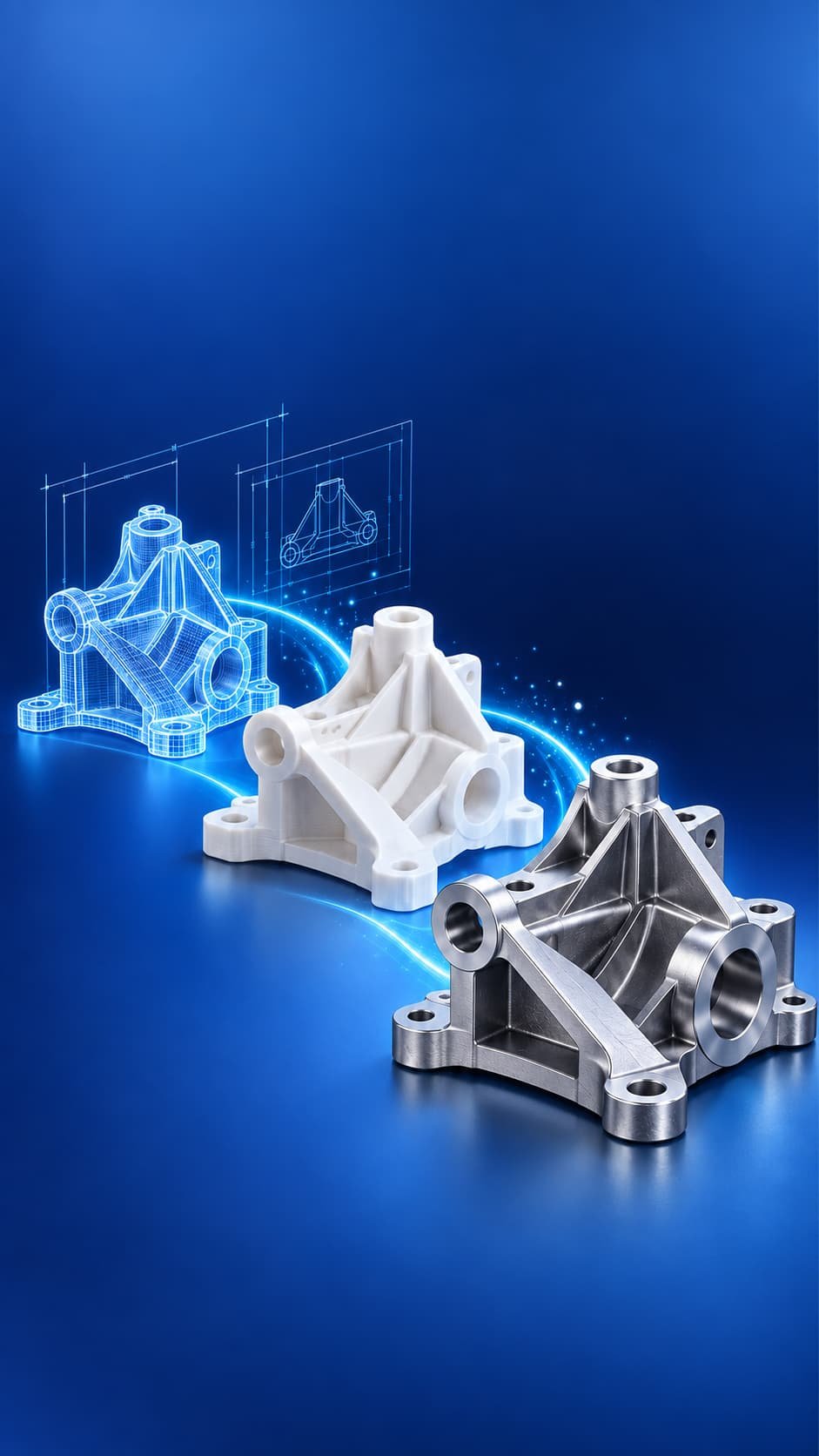
Both teams chose the right technology for the wrong requirement. SLA, SLS, and FDM are not three versions of the same process at different price points. They are three fundamentally different manufacturing technologies that excel in different dimensions of prototype performance. Understanding exactly what each process delivers on accuracy, surface finish, mechanical properties, support structures, material range, and cost tells you which one belongs on your purchase order before you place it.

Quick AnswerFDM (Fused Deposition Modeling) extrudes melted thermoplastic filament layer by layer. It is the most affordable process, best for large structural prototypes and functional parts in engineering materials like PETG, ABS, and Nylon, but produces visible layer lines and Z-axis strength 30 to 50 percent lower than XY. SLA (Stereolithography) cures liquid photopolymer resin with a UV laser to produce the finest surface finish and tightest tolerances (0.05 to 0.1mm) of the three processes, but standard resins are brittle with elongation at break of only 2 to 5 percent. SLS (Selective Laser Sintering) fuses nylon powder with a CO2 laser to produce near-isotropic parts with PA12 tensile strength of 48 to 50 MPa and no support structures required. It is the best choice for functional mechanical prototypes that must survive load, impact, and assembly testing.

How Does Each 3D Printing Process Work?

The differences in output quality between FDM, SLA, and SLS trace directly to the physics of each process. Understanding the mechanism tells you why each process produces the part quality it does, and why no amount of settings optimization closes the gap between them on the dimensions where they fundamentally differ.

FDM: Fused Deposition Modeling

FDM heats a thermoplastic filament to its melt temperature and extrudes it through a nozzle, depositing material layer by layer on a build platform. Each layer bonds to the one below by thermal fusion at the interface. As the platform lowers after each layer, the nozzle traces the next cross-section. The result is a part built from discrete plastic layers whose inter-layer bond strength is governed by how well the deposited material fuses to the previous layer at the moment of contact.

The inter-layer bond is always weaker than the material itself. Z-axis tensile strength in FDM parts is 30 to 50 percent lower than XY-plane strength in the same material, because the layer interfaces are not fully fused polymer, they are pressed contact between a hot extrudate and a cooled previous layer. Parts loaded perpendicular to the build layers fail at stresses that the same part oriented horizontally would survive. Build orientation is a structural design decision in FDM, not a printing convenience.

SLA: Stereolithography

SLA cures liquid photopolymer resin using a UV laser that traces each cross-section on the surface of a resin vat, solidifying a thin layer at a time. The build platform descends after each layer, pulling the cured part away from the vat bottom so the next resin layer can flow under it. After printing, SLA parts require washing in isopropyl alcohol to remove uncured resin, followed by UV post-cure in a curing station to fully develop mechanical properties.

The laser spot diameter and layer thickness of 25 to 100 µm determine SLA’s resolution advantage over FDM. At 25 µm layer thickness, individual layers are invisible to the naked eye and surface finish Ra values of 0.8 to 2.0 µm are achievable after post-cure. This is the primary reason SLA dominates dental, medical presentation, jewelry casting, and optical prototype applications where surface quality determines whether the prototype is usable.

SLS: Selective Laser Sintering

SLS spreads a thin layer of thermoplastic powder, typically PA12 nylon, across a heated build chamber. A CO2 laser selectively fuses the powder particles together according to the part cross-section. After each layer, the build platform drops by one layer thickness, a roller deposits fresh powder, and the laser sinters the next slice. Critically, the unsintered surrounding powder supports the part from every direction throughout the build.

That self-supporting characteristic changes the design rules for SLS completely. No support structures are required, which means internal channels, overhangs in every direction, interlocking assemblies, and complex organic geometry are all printable without any post-processing to remove supports. The absence of layer-direction bonding weakness is the second critical difference: SLS parts are near-isotropic. PA12 loses only approximately 6 percent of tensile strength in its weakest orientation compared to its strongest, a value that compares favorably to injection-molded parts.

How Do FDM, SLA, and SLS Compare Across Every Dimension That Matters?

The table below compares all three processes on the ten criteria that product engineers and procurement teams use most frequently when selecting a 3D printing technology for prototype and low-volume production applications.

Comparison CriterionFDMSLASLS
Dimensional Tolerance0.2 to 0.5mm0.05 to 0.1mm0.1 to 0.3mm
Layer Thickness0.1 to 0.3mm0.025 to 0.1mm0.08 to 0.15mm
Surface Finish (as-printed Ra)12 to 25 µm (visible layer lines)0.8 to 2.0 µm (near-smooth)8 to 15 µm (slightly grainy)
Mechanical IsotropyAnisotropic (Z 30 to 50% weaker)Anisotropic (Z slightly weaker)Near-isotropic (Z 6% weaker)
Tensile Strength (typical)40 to 60 MPa (XY), 20 to 35 MPa (Z)25 to 65 MPa (resin-dependent)48 to 50 MPa (near-uniform all axes)
Elongation at Break3 to 8% (brittle at layer lines)2 to 5% standard resin, 8 to 15% tough resin15 to 20% (PA12, excellent ductility)
Support Structures RequiredYes (for overhangs beyond 45 degrees)Yes (for most overhangs)No (powder self-supports)
Primary MaterialsPLA, ABS, PETG, Nylon, TPU, PEEK, PCPhotopolymer resins (standard, tough, flexible, dental, castable)PA12 nylon, PA11, TPU, glass-filled nylon
Typical Cost per cm3USD 0.10 to USD 0.40USD 0.15 to USD 0.60USD 0.40 to USD 1.20
Lead Time (bureau service)1 to 3 days1 to 3 days3 to 7 days (includes powder recovery)
Best Prototype TypeLarge structural, jigs, fixtures, concept modelsVisual models, dental, optical, fine-detail partsFunctional mechanical, load-bearing, snap-fits, assemblies
Worst Use CaseFine detail, smooth surface, impact-critical partsImpact or fatigue-critical functional testingLarge flat panels, high-gloss cosmetic surface

Where Does Each Process Win, and Where Does Each Fail?

Where FDM Is the Right Choice

FDM is correct when part size is large, material choice is the primary driver, or budget is the hard constraint. A 400mm structural bracket for a machine fixture does not need SLA surface finish and cannot justify SLS cost at a single prototype quantity. FDM in PETG or Nylon produces a part that fits, mounts, and functions structurally at a fraction of the cost of the other two processes.

FDM is also the only polymer 3D printing process that handles high-performance engineering thermoplastics at the desktop level. PEEK filament processed at 380 degrees Celsius nozzle temperature produces parts with continuous service temperatures above 250 degrees Celsius and tensile strength approaching 100 MPa. No resin and no PA12 powder competes with PEEK on thermal resistance. For prototypes that must survive elevated temperatures, FDM with the correct filament is often the only viable polymer 3D printing option.

Where FDM fails: any application requiring tight tolerances, smooth surfaces, isotropic mechanical properties, complex overhangs without extensive support, or high elongation before failure. A snap-fit clip designed to flex repeatedly will fail at the layer interfaces long before the material itself yields. A visual presentation model with FDM layer lines visible at 1 meter will not pass client review.

Where SLA Is the Right Choice

SLA is correct when surface finish and dimensional accuracy are the primary requirements. Dental restoration models, hearing aid shells, jewelry casting patterns, microfluidic device prototypes, and optical system housings all require surface quality that FDM and SLS cannot match. SLA at 25 µm layer thickness produces surfaces that require minimal sanding before painting, plating, or presentation.

SLA resins cover a wider property range than most engineers realize. Standard resins deliver 65 MPa tensile strength at only 2 to 5 percent elongation, making them brittle under impact. Tough resins push elongation to 8 to 15 percent while maintaining strength. Flexible resins produce rubber-like behavior. Biocompatible and dental-certified resins exist for medical device and surgical guide applications. Castable resins burn out cleanly for lost-resin metal casting. The material range, combined with SLA’s accuracy advantage, makes it the dominant technology in dental and medical additive manufacturing [1].

Where SLA fails: any application requiring impact resistance, repeated mechanical cycling, ductile failure mode, long-term UV stability, or elevated service temperatures. Standard SLA resins creep under sustained load and degrade with prolonged UV exposure. A functional bracket that will be drop-tested, assembled with snap fits, or used outdoors should not be SLA.

Where SLS Is the Right Choice

SLS is correct when the prototype must behave mechanically like a production part. PA12 nylon from SLS achieves tensile strength of 48 to 50 MPa and elongation at break of 15 to 20 percent, properties nearly identical to injection-molded PA12. Parts can be assembled, snap-fitted, torqued with fasteners, and drop-tested without premature failure from layer interface weakness.

The self-supporting nature of SLS powder bed removes all geometric constraints related to support access. Internal lattice structures, conformal cooling channels, hinged assemblies, and parts nested inside other parts can all be printed and removed from the powder bed as single-shot assemblies without any post-processing support removal. For complex assemblies that would require extensive support removal time in SLA or FDM, SLS eliminates the post-processing step entirely [2].

SLS is also the most cost-effective 3D printing option for small batches of 10 to 100 parts, because the build volume can be packed densely with multiple parts in a single build. Unlike SLA and FDM where build time scales with part volume, SLS build time scales primarily with build height, so packing the chamber maximizes output per build cycle.

Where SLS fails: high-gloss cosmetic surfaces, tight tolerances below 0.1mm, and large flat panels where thermal gradients during sintering cause subtle warpage. If the prototype must look like an injection-molded part without painting or bead blasting, SLS cannot deliver that surface quality directly from the printer.

Which Process Should You Choose for Your Specific Application?

Use the decision framework below to map your prototype requirement to the correct process before placing an order.

Your RequirementChoose This ProcessReason
Visual presentation model, client review, smooth surfaceSLABest surface finish of all three, minimal post-processing for cosmetic quality
Functional mechanical prototype, snap fits, assembly testingSLSNear-isotropic PA12 strength 48 to 50 MPa, 15 to 20% elongation, no layer failure
Large structural bracket, jig, or fixtureFDMLowest cost at large volumes, adequate strength in XY plane for structural applications
Dental model, surgical guide, hearing aid shellSLABiocompatible and dental-certified resin grades, finest dimensional accuracy
Complex geometry with internal channels, no supportsSLSSelf-supporting powder bed enables any geometry without support removal
Engineering thermoplastic prototype (PEEK, Ultem, PC)FDMOnly polymer 3D printing process for high-temperature engineering filaments
10 to 100 units of a functional nylon partSLSNear-injection-molded PA12 properties, cost-effective batch building in packed chamber
Jewelry casting pattern or optical prototypeSLACastable resin grades, finest layer resolution, smooth surface for optical clarity
Drop-test prototype or impact-critical partSLSPA12 ductility (15 to 20% elongation) absorbs impact. SLA and FDM are brittle at interfaces.
Prototype that must survive elevated temperature above 150CFDM with PEEK or Ultem filamentNo SLA resin or SLS nylon approaches PEEK’s 250 degrees C service temperature
Not Sure Which 3D Printing Process Your Prototype Needs?Upload your STEP or STL file to Elite Mold Tech and receive a free process recommendation within 12 hours. Our engineering team reviews your geometry, material requirement, mechanical performance criteria, and surface finish specification to identify whether FDM, SLA, or SLS is the right fit, with a quote for each option so you can compare total cost against your requirement. All uploads are secure and NDA protection is available on request.Visit elitemoldtech.com to explore 3D printing services and upload your CAD file.

Related Elite Mold Tech Guides and Sources

Related guides: complete manufacturing process selector guide, DMLS metal 3D printing guide, SLA 3D printing services.

Authoritative references: ISO/ASTM 52900 additive manufacturing standard, ASTM International additive standards.

Get a DFM Review from Elite Mold Tech

Ready to move from drawing to part? Upload your CAD file to Elite Mold Tech and receive a DFM review within 12 hours, with tolerance, material, and cost feedback from our engineering team before you commit to tooling.

Часто задаваемые вопросы

Can SLA prototypes be used for functional mechanical testing?

SLA prototypes can be used for some functional testing, but their brittle failure mode under impact and low elongation at break of 2 to 5 percent in standard resins disqualify them from most mechanical load and drop tests. Standard SLA resins fail by brittle fracture under impact loads that equivalent SLS or injection-molded nylon parts would absorb and survive. For static loading tests where the part is loaded gradually to failure, SLA provides useful data because tensile strength of 25 to 65 MPa is meaningful. For fatigue testing, drop testing, snap-fit cycling, or any test that applies rapid loading, SLA is not the correct process. Tough and engineering-grade SLA resins improve elongation to 8 to 15 percent and reduce brittleness, but they remain significantly less ductile than SLS PA12 nylon at 15 to 20 percent elongation. The correct process for functional mechanical testing is SLS for polymer prototypes, or CNC machining in the actual production material for the highest fidelity mechanical test data.

Why does SLS cost more per part than FDM or SLA at low quantities?

SLS costs more per part at low quantities for three compounding reasons. First, machine cost: industrial SLS systems cost USD 50,000 to USD 500,000 versus USD 200 to USD 5,000 for desktop FDM and SLA printers, and that capital cost must be recovered through per-part pricing at commercial bureaus. Second, powder management: SLS requires a controlled-atmosphere heated build chamber, powder spreading, and powder recovery after each build, consuming operator time and consumable powder regardless of how many parts are in the chamber. Third, post-processing: SLS parts require bead blasting or vapor smoothing and powder removal from every internal feature after printing, adding time and equipment cost. The economics improve dramatically when the chamber is densely packed with multiple parts sharing the fixed build overhead. An SLS chamber packed with 50 parts distributes the fixed build cost across all 50, bringing per-part cost toward parity with SLA at similar quantities. At 1 to 3 parts, SLS is most expensive. At 20 to 100 parts in a packed chamber, it becomes cost-competitive with alternatives for functional nylon components.

What is the difference between FDM and FFF 3D printing?

FDM (Fused Deposition Modeling) and FFF (Fused Filament Fabrication) describe the same process. FDM is a trademarked term owned by Stratasys, the company that invented and patented the technology in the late 1980s. When the patents expired and the technology became widely available, manufacturers producing machines that use the same extrusion process called it FFF to avoid the trademark. In practice, the process is identical: melted thermoplastic filament is extruded through a nozzle and deposited layer by layer. The difference is entirely commercial, not technical. Industrial FDM machines from Stratasys use proprietary build materials and achieve tighter tolerances (Stratasys documents accuracy of 0.089mm on the F900) than most desktop FFF machines, but this reflects machine quality, material consistency, and build chamber control rather than any fundamental process difference. In the industry, the terms are used interchangeably and the distinction matters only in legal and trademark contexts.

How does support removal work in SLA and FDM, and does it affect part quality?

In SLA, supports are thin resin columns generated automatically by the slicing software to prevent uncured resin from sagging during the build. After printing, supports are removed manually by cutting or breaking them off. The contact points where supports attached leave small witness marks on the part surface, typically pits or flat spots of 0.5 to 2mm that require sanding to restore surface quality. This means any surface in an SLA part that faces downward during the build (requiring supports) will have lower surface quality than upward-facing surfaces, making build orientation a cosmetic design decision. In FDM, supports are printed in the same material as the part or in a soluble support material. Break-away supports leave similar witness marks. Soluble supports dissolve cleanly in water or solvent, leaving clean surfaces, but add material cost and require a dual-extrusion printer. In SLS, no supports are required at all. The unsintered powder cradling the part from every direction during the build means every surface of an SLS part has the same quality, defined only by the laser sintering resolution and powder particle size. This is one of the most significant practical advantages of SLS over the other two technologies for complex geometries.

Can 3D printed prototypes be used as tooling for injection molding?

3D printed parts are used as injection mold tooling in specific, limited circumstances and with clear expectations about tool life and output quality. SLA or specialized resin parts are used as bridge injection mold inserts for very short runs of 50 to 200 shots at low injection pressures and reduced cycle speeds. The resin cannot withstand the full injection pressure and temperature of production molding, so the process parameters must be adjusted, which affects the output parts. SLS nylon and reinforced FDM prints have been used as conformal cooling inserts and core pins for similar short-run applications. Metal-filled FDM materials and direct metal 3D printing (DMLS) are more appropriate for tooling that must survive production cycles. The primary use case for 3D printed tooling is market validation: getting 50 to 200 molded plastic parts before committing USD 8,000 to USD 40,000 to a production aluminum or steel mold. For any significant production volume, proper injection mold tooling is always the correct answer.

Is SLS nylon suitable as a direct replacement for injection-molded nylon parts in production?

SLS nylon PA12 is used in direct production applications in aerospace, automotive, and medical device manufacturing where part volumes are too low to justify injection mold tooling, geometry is too complex for conventional molding, or lead time requirements cannot accommodate mold fabrication. SLS PA12 achieves tensile strength of 48 to 50 MPa and elongation at break of 15 to 20 percent, which are near-identical to injection-molded PA12 mechanical properties. The differences are surface finish (SLS is grainier than molded PA12 without post-processing), dimensional consistency across large batches (injection molding is more repeatable shot-to-shot), and per-part cost at volume above 5,000 units (injection molding becomes cheaper per part as tooling cost amortizes). For volumes under 500 to 1,000 units where the geometry justifies it, SLS PA12 is a genuine production process, not merely a prototyping shortcut. Elite Mold Tech uses SLS for low-volume production components alongside CNC machining and injection molding, selecting the process based on volume, geometry, and mechanical requirement of each specific part.

About the Author:
Alex Morgan specializes in technical content for precision manufacturing, with a focus on CNC machining, injection molding, die casting, 3D printing, sheet metal fabrication, and custom mold manufacturing. With more than a decade of experience in B2B manufacturing content and SEO, he creates technically accurate content designed for engineers, product developers, procurement teams, and manufacturing decision-makers. His work helps global manufacturers clearly communicate complex production capabilities, material options, tolerances, tooling processes, and quality standards to customers across the US, Europe, and Asia-Pacific. He writes for manufacturing companies where technical expertise, precision, and reliability matter.

Elite Mold Tech

Вам нужны квалифицированные решения в области механической обработки? Наша команда в Elite Mold Tech готова помочь вам во всех производственных нуждах. Свяжитесь с нами сегодня, чтобы получить предложение по вашим текущим или предстоящим проектам!

Свяжитесь с нами

Воплощайте свои проекты в жизнь с Elite Mold Tech

Испытайте прецизионную обработку с ЧПУ с Elite Mold Tech. От сложных прототипов до крупномасштабного производства - мы готовы воплотить ваши идеи в реальность. Свяжитесь с нами сегодня, чтобы обсудить потребности вашего проекта!

Свяжитесь с нами!
Оперативный ответ гарантирован в течение 12 часов
🔐 Все загрузки безопасны и конфиденциальны

Экспертные мнения и тенденции отрасли
Изучайте передовые технологии производства вместе с Elite Mold Tech. В наших блогах вы найдете мнения экспертов, тенденции развития отрасли и практические советы по повышению эффективности, точности и инновационности ваших производственных процессов.
Свяжитесь с нами!
Оперативный ответ гарантирован в течение 12 часов
🔐 Все загрузки безопасны и конфиденциальны