A product team submits a CAD file on Monday expecting a quote by Wednesday and parts the following week. Instead, three separate emails go back and forth clarifying tolerance callouts that were never specified, the quote takes five days because nobody flagged which dimensions were actually critical, and the first sample arrives with a wall thickness that technically matches the drawing but was never going to survive the drop test it needed to pass.
None of this is unusual. It is what happens when a rapid prototyping request skips the structure that turns a CAD file into an approved, functional sample efficiently. The process is not complicated, but it has a specific sequence, and skipping steps in that sequence is the single biggest cause of prototyping delays, miscommunication, and wasted iterations. CNC machining vs injection molding vs 3D printing
This guide walks through the complete rapid prototyping process from initial CAD submission to final sample approval, covering exactly what information a manufacturer needs at each stage, what DFM review actually checks for, how process selection gets decided, and what a proper first article inspection report should contain before you sign off and move toward production.
| 간단한 답변 The rapid prototyping process runs through six stages: (1) CAD file submission with a clear statement of what the prototype needs to validate, (2) DFM review checking tolerance feasibility, wall thickness, and manufacturability, (3) process and material selection matched to the validation goal, (4) manufacturing (CNC machining, 3D printing, or a combination), (5) inspection and first article reporting against the drawing, and (6) sample approval or a documented revision cycle if issues are found. Standard lead time from file submission to first parts is 3 to 10 business days depending on process and complexity. Skipping the DFM review or submitting a CAD file without clear critical dimensions and validation goals is the most common cause of prototyping delays and failed first samples. |
The 6-Step Rapid Prototyping Process
1단계: Submit a Complete CAD File With a Clear Validation Goal
Every prototyping request should include the 3D CAD file in the correct format (STEP for CNC machining, STL or 3MF for most 3D printing processes, and both a 3D model and a 2D drawing if critical tolerances exist that the 3D model alone does not communicate), the file revision number, and a specific statement of what question the prototype needs to answer. A prototype requested to check fit and form against a mating enclosure has entirely different priorities than a prototype requested to validate mechanical strength under load. Stating the goal upfront lets the manufacturer recommend the right process and material rather than defaulting to whatever is fastest or cheapest. Critical dimensions should be called out explicitly on the drawing with acceptable tolerance ranges, since without this information, every dimension is treated with the same priority and genuinely critical features can be missed during inspection.
2단계: DFM Review Confirms Manufacturability Before Production Starts
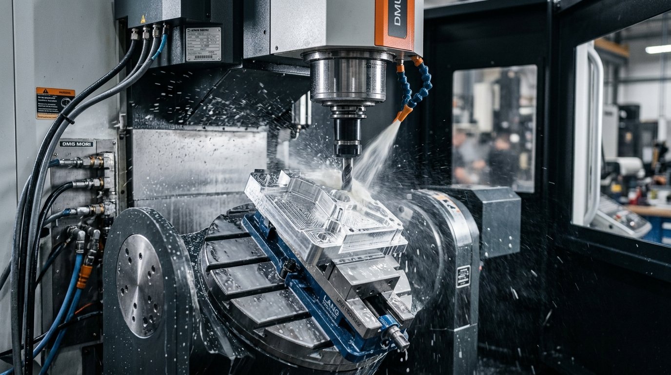
Design for Manufacturability review checks the submitted geometry against the physical constraints of the proposed manufacturing process before any material is cut or printed. For CNC machining, this means checking wall thickness against tool access, verifying that specified tolerances are achievable with standard tooling or require special setups, and flagging any features that cannot be reached without additional fixturing. For 3D printing, DFM review checks minimum wall thickness for the chosen technology, support structure requirements for overhangs, and whether the part orientation in the build affects a critical surface. A thorough DFM review at this stage catches problems that would otherwise surface only after the prototype is built and fails inspection, at which point an iteration cycle of days to weeks has been consumed for nothing.
Step 3: Process and Material Selection Matched to the Validation Goal
With the validation goal and DFM findings established, the correct manufacturing process becomes a straightforward decision rather than a default choice. A visual fit-check prototype with no mechanical requirement might be built fastest and cheapest in SLA or FDM. A functional prototype that will be drop-tested or assembled with snap fits needs SLS nylon or CNC machining tolerances in the actual production-intent material. A prototype intended to validate injection molding tooling decisions before committing USD 20,000 to USD 80,000 to steel needs to be built in the exact resin grade specified for production, since substituting a similar-but-different material can produce misleading results on shrinkage, warpage, and mechanical performance. This is the stage where an experienced manufacturing partner adds the most value: recommending against a process the customer requested because it will not actually validate what they need to know.
4단계: Manufacturing Produces the Physical Prototype
Once process and material are confirmed, manufacturing begins. Lead time varies by process: CNC machining and most 3D printing technologies typically deliver first parts in 3 to 10 business days depending on part complexity and current shop capacity. Multi-material assemblies, parts requiring secondary finishing (anodizing, painting, plating), or complex 5-axis geometry extend this timeline. If multiple prototype iterations are anticipated, which is common on any first-time design, discussing the expected number of revision cycles upfront helps set realistic program timeline expectations rather than treating each iteration as an unplanned delay.
Step 5: Inspection and First Article Reporting Verify the Part Against the Drawing
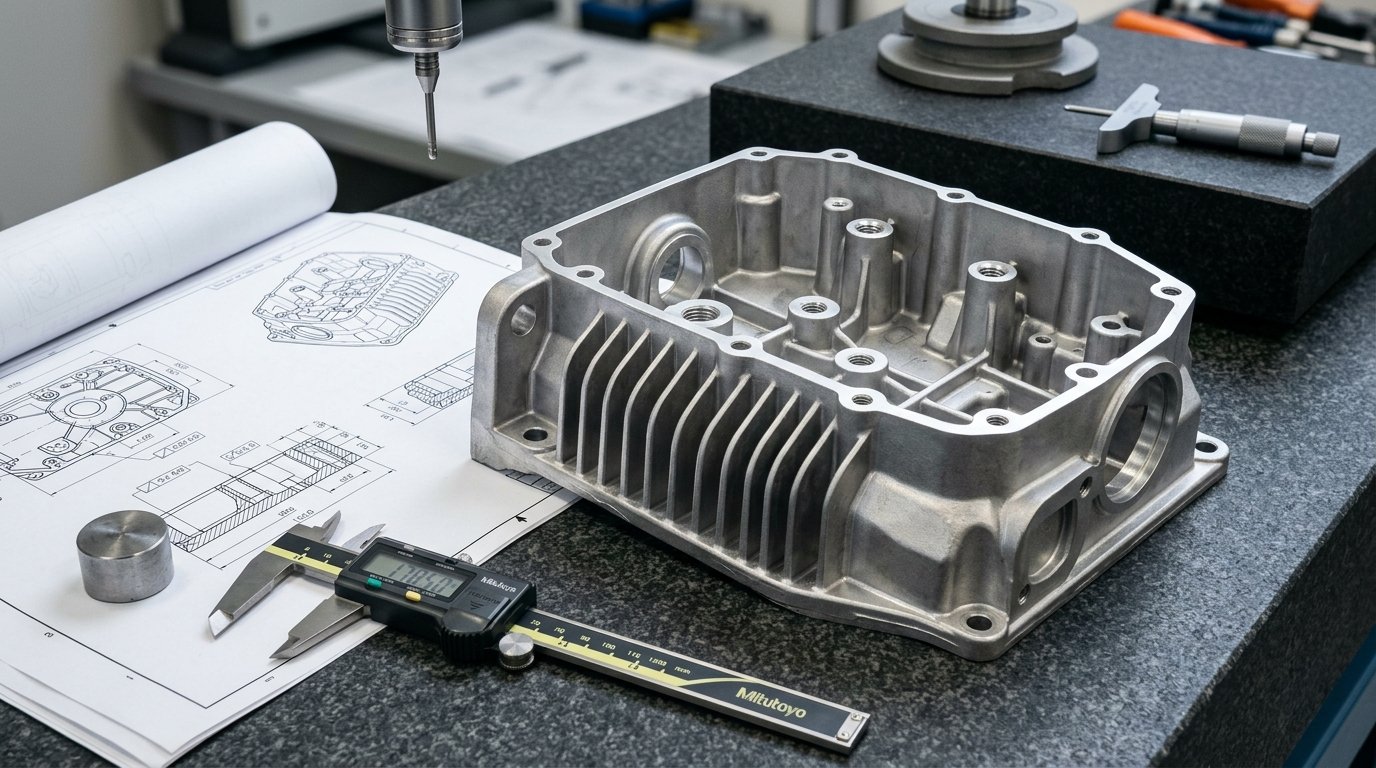
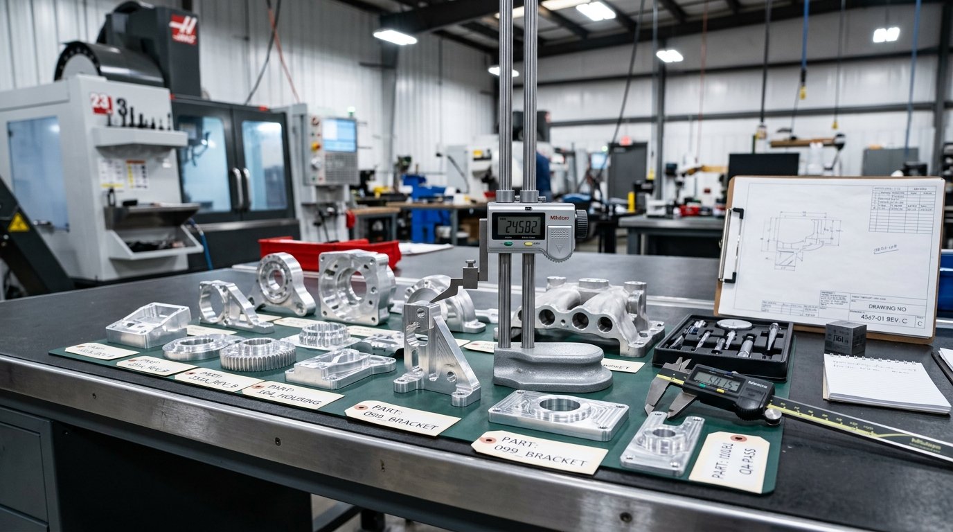
Before a prototype is shipped or presented as approved, it should be measured against the drawing, not just visually reviewed. For simple parts with loose tolerances, a basic caliper check of critical dimensions may be adequate. For parts with tight tolerances or complex geometric requirements, a formal inspection using CMM (Coordinate Measuring Machine) equipment produces a documented report mapping every measured dimension against its drawing callout. This report is what allows an engineering team to make an informed approve or reject decision, rather than approving based on visual appearance alone and discovering a dimensional problem later at assembly or in a larger production run.
Step 6: Approval or Documented Revision Cycle
If the prototype passes inspection and meets the stated validation goal, formal written approval closes this stage and the project moves toward the next stage of development, whether that is further testing, tooling authorization, or additional prototype iterations addressing new questions. If issues are found, they should be documented specifically (which dimension, which feature, what the measured value was versus the drawing requirement) so the design revision addresses the actual root cause rather than a general impression that “it did not fit right.” A clear engineering change record at this stage prevents the same issue from resurfacing in a later iteration because the specific cause was never precisely identified.
How Long Does Each Stage of the Rapid Prototyping Process Take?
Realistic timeline expectations prevent the most common source of program friction: assuming a prototype will arrive faster than the process actually allows. The table below reflects typical durations at each stage across common prototyping scenarios.
| 프로세스 단계 | Simple Part (single feature, loose tolerance) | Moderate Part (multiple features, precision fit) | Complex Part (multi-material, tight tolerance) |
|---|---|---|---|
| CAD Review and Quote | Same day to 1 business day | 1 to 2 business days | 2 to 3 business days |
| DFM Review | Included in quote, same day | 1 business day | 1 to 2 business days |
| Manufacturing (CNC or 3D print) | 1 to 3 business days | 3 to 5 business days | 5 to 10 business days |
| Inspection and Reporting | Same day (basic check) | 1 business day (CMM report) | 1 to 2 business days (full FAI) |
| Total Typical Lead Time | 2 to 5 business days | 5 to 8 business days | 8 to 15 business days |
Which Prototyping Process Should You Choose Based on What You Need to Validate?
| Validation Goal | 권장 절차 | 왜 |
|---|---|---|
| Visual form check, presentation, or client review | SLA or high-detail FDM | Best surface finish and dimensional accuracy for cosmetic review |
| Fit and assembly check against mating parts | FDM or CNC machining | Adequate accuracy at lower cost than production-grade tolerance requirements |
| Functional mechanical testing (load, drop, assembly cycling) | SLS nylon or CNC machining in production-intent material | Isotropic strength and realistic material behavior under load |
| Injection mold cost tooling validation before steel commitment | CNC machining in exact production resin, or aluminum bridge tool | Only actual production material and process reveal true shrinkage and warpage behavior |
| Regulatory or customer approval sample | CNC machining or production-intent process with full CMM inspection | Documented dimensional traceability required for formal sign-off |
| Complex internal geometry not achievable by machining | SLS or DMLS (for metal) | Self-supporting powder bed process reaches geometry CNC tooling cannot |
| Ready to Move Your CAD File Into Production Prototyping?Upload your STEP, STL, or IGES file to Elite Mold Tech and receive a full DFM review with process recommendation and quote within 12 hours. Our engineering team will confirm critical tolerances, recommend the right process for your specific validation goal, and provide a documented inspection report with every sample. All uploads are secure and NDA protection is available on request.Visit elitemoldtech.com to upload your file and start your prototyping project. |
관련 엘리트 몰드 테크 가이드 및 참고 자료
관련 가이드: 전체 제조 공정 선택 가이드, SLA, SLS, FDM 비교, rapid prototyping services.
신뢰할 수 있는 참고 자료: 제조공학자협회(SME), ISO 2768-1 일반 공차 표준.
Elite Mold Tech에서 DFM 검토를 받아보세요
도면에서 실제 부품 제작으로 넘어갈 준비가 되셨나요? Elite Mold Tech에 CAD 파일을 업로드하시면, 금형 제작을 확정하기 전에 당사 엔지니어링 팀으로부터 공차, 소재 및 비용에 대한 피드백이 포함된 DFM 검토 결과를 12시간 이내에 받아보실 수 있습니다.
자주 묻는 질문
What information should I include with my CAD file to get the fastest and most accurate quote?
The fastest, most accurate quotes come from submissions that include the 3D CAD file in the correct native or neutral format (STEP for CNC machining, STL or 3MF for most 3D printing), a 2D drawing if any dimension has a tolerance tighter than general industry default, explicit critical dimensions with their acceptable tolerance range called out rather than left to be assumed, the intended material or a functional requirement the material must meet if you are not certain which material to specify, the quantity needed, and a brief statement of what the prototype needs to validate or prove. Submissions missing critical tolerance callouts are the single most common cause of quote delays, because the manufacturer must either guess at tolerance requirements (risking a part that does not meet an unstated need) or pause the quote to ask a clarifying question, adding a full communication cycle to the timeline before manufacturing even begins.
How many prototype iterations should I expect before a design is ready for production?
The number of iterations depends heavily on design maturity and part complexity, but two to four iterations is a realistic range for most first-time designs of moderate complexity. A first iteration commonly reveals fit or assembly issues that were not apparent in CAD review alone. A second iteration addresses those issues and may surface a secondary problem, often related to tolerance stack-up across multiple mating features or a material property that behaves differently than assumed under real conditions. By the third iteration, most designs converge on a version that passes functional testing and dimensional inspection. Highly complex assemblies, novel mechanisms, or designs with tight multi-part tolerance stacks can require more iterations. Budgeting for at least two rounds of prototyping in your program timeline, rather than assuming the first sample will be production-ready, prevents the most common source of schedule slippage in new product development.
Should I request a formal CMM inspection report on every prototype, or is visual review sufficient?
The decision depends on the tolerance requirements and the consequence of an undetected dimensional error. For simple parts with loose general tolerances and no critical mating features, a basic caliper check of a few key dimensions is usually adequate and keeps cost and lead time down. For any part with tolerances tighter than 0.1mm, geometric requirements controlled by GD&T callouts, or features that must mate precisely with another component, a formal CMM inspection report mapping every critical dimension against the drawing is worth the additional cost and the typically one additional business day it adds to the process. The report becomes the documented basis for an approve or reject decision and creates a clear record if a dimensional issue needs to be traced later, rather than relying on a visual impression that a part “looks right.”
What is the difference between a prototype and a first article inspection sample?
A prototype is any physical part produced to validate a design question, which may or may not include formal dimensional documentation, and is often produced through 3D printing or a lower-cost process not intended to represent final production conditions. A First Article Inspection (FAI) sample, by contrast, is specifically produced using the intended production process and material, with every dimension and characteristic on the engineering drawing measured and documented in a structured report, providing objective evidence that the production process can reliably meet specification before a full production quantity is authorized. In practice, a design typically moves through several early prototypes using faster, cheaper processes to validate form, fit, and basic function, and then a final FAI sample using the actual production process and material to formally validate the production method itself before volume manufacturing begins. Confusing the two, treating an early 3D-printed prototype as equivalent to a production-process FAI sample, is a common source of surprises when the production process behaves differently than the prototype process did.
How do I protect my design when sending CAD files for prototyping quotes to multiple manufacturers?
A signed NDA (Non-Disclosure Agreement) before sharing detailed CAD files is standard practice, and any legitimate manufacturer should sign one without resistance or significant delay. Beyond the NDA, practical steps include sharing only the geometry needed for an accurate quote rather than full assembly context if the design includes proprietary elements unrelated to the specific part being quoted, watermarking or limiting file metadata where the CAD software allows it, and being selective about how many manufacturers receive the full detailed file versus a simplified geometry sufficient for an initial rough quote. For designs with significant IP value, limiting the number of manufacturers who receive the complete file to those who have passed basic due diligence, rather than mass-distributing the file to every quote request platform, reduces exposure while still allowing competitive quoting.
What happens if the prototype passes dimensional inspection but fails functional testing?
A part that is dimensionally within tolerance but fails a functional test (drop test, load test, assembly cycling, environmental exposure) points to a design or material specification problem rather than a manufacturing process error, since the manufacturer produced the part correctly to the drawing. This is a critical and common finding that DFM review at the CAD stage cannot always catch, because DFM review confirms manufacturability, not functional performance under real-world conditions. When this happens, the design team needs to determine whether the material specification was inadequate for the actual load case, whether a design feature (wall thickness, rib placement, fastener boss design) needs reinforcement, or whether the drawing tolerance itself needs tightening to ensure consistent functional performance across the full population of parts, not just the specific sample tested. This is precisely why prototyping and DFM review exist: to surface this exact gap between “meets the drawing” and “performs the function” while a design change costs engineering time rather than a failed product in the field.
저자 소개:
알렉스 모건은 정밀 제조 분야의 기술 콘텐츠 전문 작가로, 특히 CNC 가공, 사출 성형, 다이캐스팅, 3D 프린팅, 판금 가공, 맞춤형 금형 제조 분야에 중점을 두고 있습니다. B2B 제조 콘텐츠 및 SEO 분야에서 10년 이상의 경력을 쌓아온 그는 엔지니어, 제품 개발자, 조달 팀, 제조 분야 의사결정권자를 대상으로 기술적으로 정확한 콘텐츠를 제작합니다. 그의 작업은 전 세계 제조업체들이 미국, 유럽, 아시아태평양 지역의 고객들에게 복잡한 생산 역량, 소재 옵션, 공차, 금형 공정 및 품질 기준을 명확하게 전달할 수 있도록 돕습니다. 그는 기술적 전문성, 정밀성, 신뢰성이 중요한 제조 기업들을 위해 글을 씁니다.