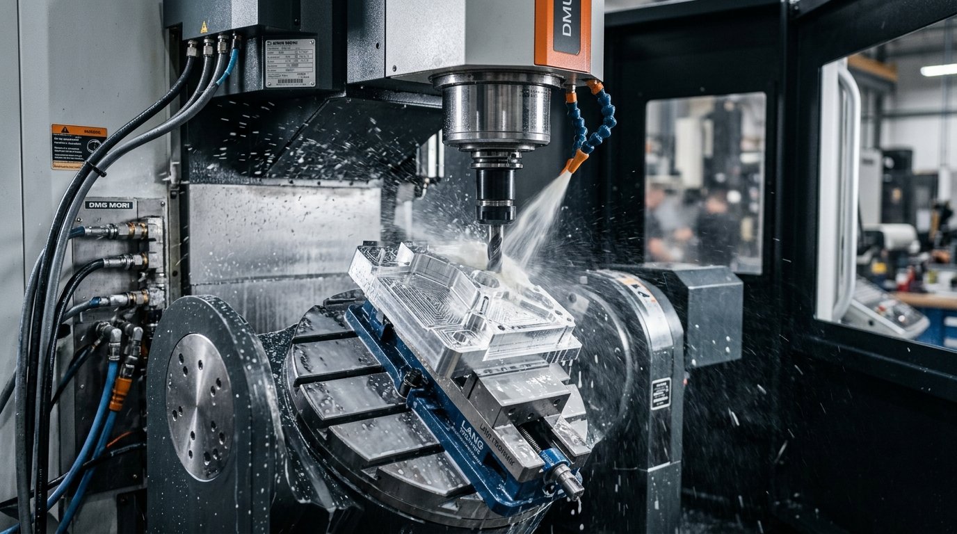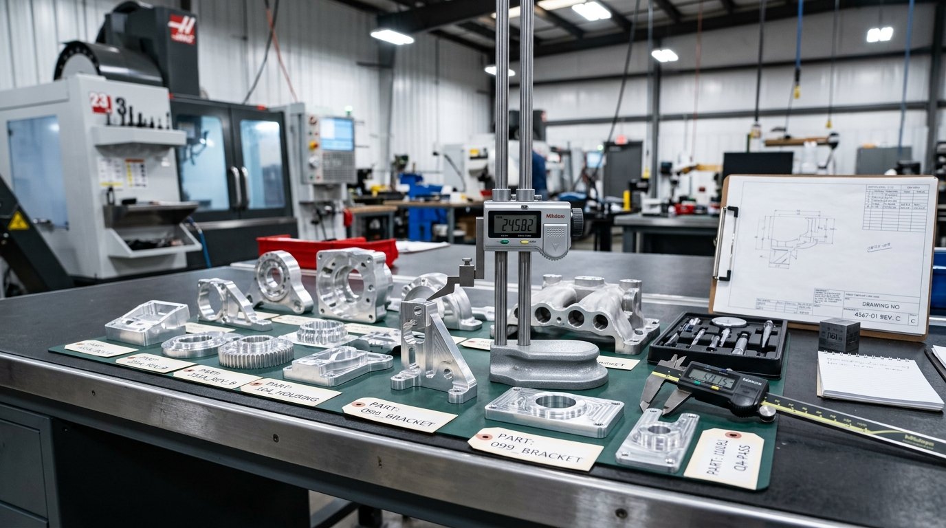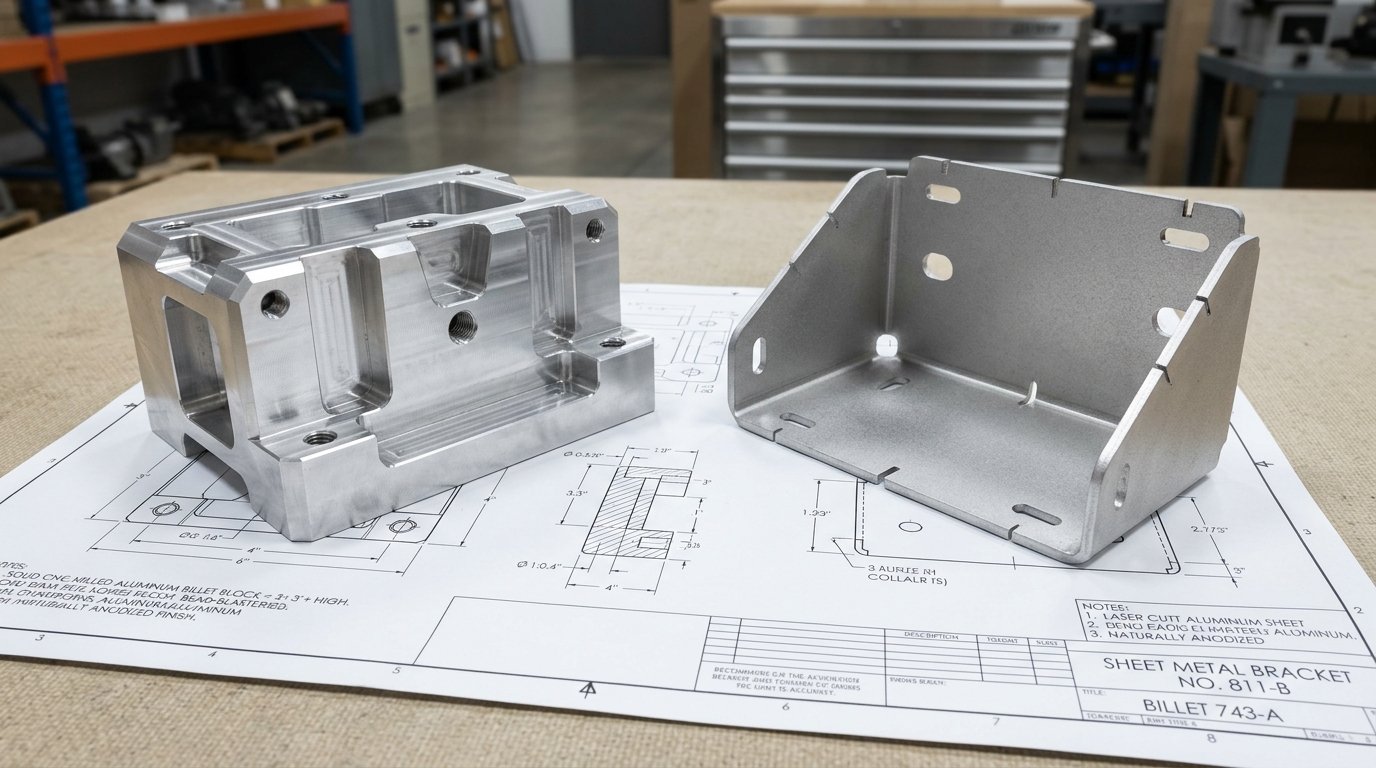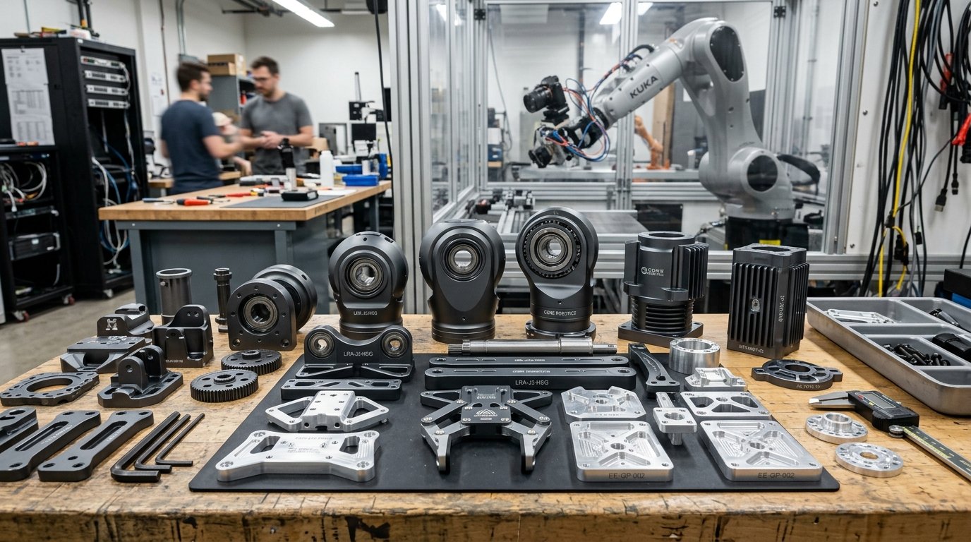
Aluminum CNC machining for robotics covers the structural and precision parts that hold a robot together: joint housings, arm links, motor and gearbox mounts, end-of-arm tooling plates, sensor brackets and automation fixtures. Aluminum is the default because it’s light, stiff enough, quick to machine and easy to finish. The parts that matter most are the ones with bearing bores, mounting faces and dowel holes, because small errors there stack up through every joint.
The short version: use 6061-T6 for most frames, brackets and fixtures, 7075-T6 for highly loaded links and joints, and spend your tolerance budget on bores, datums and mating faces rather than on every dimension.
Why Use Aluminum CNC Machining for Robotics?
Robots move their own structure. Every gram in an arm link or end effector has to be accelerated, stopped and held in place by motors and gearboxes. That’s why weight matters more in robotics than in most machinery.
Aluminum alloys hit a useful balance:
- Low density. Aluminum weighs about a third as much as steel for the same volume, which lowers inertia and lets smaller motors do the work.
- Machinability. It cuts fast, so pocketed, ribbed and lightweighted parts stay affordable.
- Thermal conductivity. Motor and electronics heat spreads through aluminum housings instead of building up.
- Finishing. Anodizing gives corrosion and wear protection and a clean appearance for cobots and consumer-facing machines.
- Availability. Plate and bar in 6061 and 7075 are stocked almost everywhere.
Steel still has its place for shafts, gears and high-wear parts. Engineering plastics such as POM work for guides and bushings. But for the structure that connects everything, aluminum is usually first choice.
Which Robot and Automation Parts Are CNC Machined?
| 구성 요소 | Typical alloy | What makes it demanding |
| Joint housing | 6061-T6 or 7075-T6 | Coaxial bearing bores, perpendicular mounting faces |
| Arm link / segment | 7075-T6 or 6061-T6 | Stiffness-to-weight, pocketing, thin ribs |
| Motor and gearbox mount | 6061-T6 | Pilot diameter, bolt circle position, flatness |
| End-of-arm tooling (EOAT) plate | 6061-T6 | Standard bolt pattern, dowel holes, flatness |
| Gripper fingers and jaws | 7075-T6 or 6061-T6 | Wear on contact faces, small features |
| Encoder and sensor bracket | 6061-T6 | Position relative to the shaft axis |
| Linear axis carriage plate | 6061-T6 or MIC-6 | Flatness across rail mounting surfaces |
| Automation fixtures and nests | 6061-T6 or MIC-6 | Repeatable location, hardened inserts where parts wear |
| Mobile robot chassis parts | 6061-T6 | Mixed machined and 판금 construction |
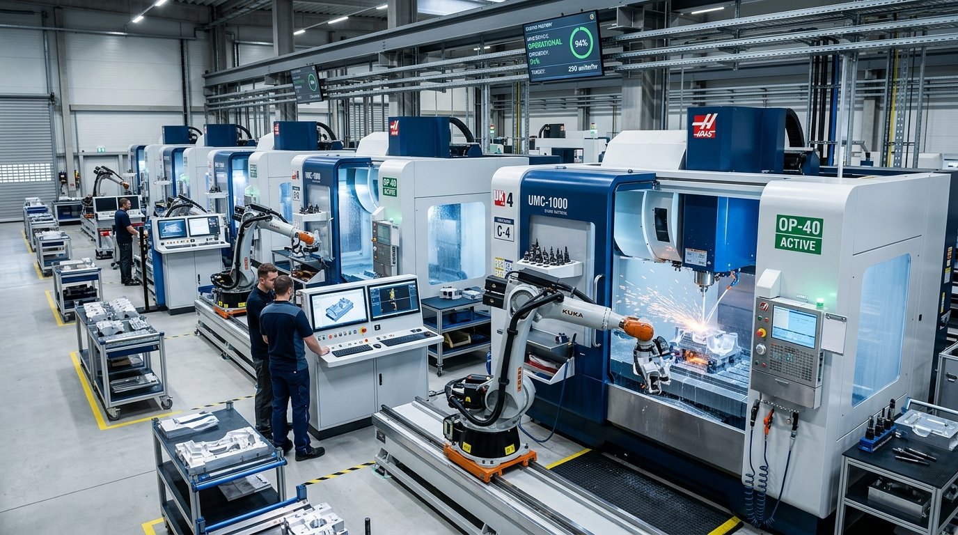
These parts often move from a 5-piece prototype to 50- or 500-piece batches quickly. Consistency between those batches matters as much as the first part.
6061 vs 7075: Choosing the Right Alloy for Robot Parts
6061-T6 is the workhorse. It’s the right choice for most brackets, plates, mounts, fixtures and housings. It machines cleanly, anodizes evenly, resists corrosion well, and costs less than 7075.
7075-T6 is the high-strength option. Choose it when a part carries high loads at a small cross-section, for example a slim arm link, a high-torque joint housing, or gripper fingers that take repeated impact. It’s more expensive, slightly harder on tools, and its anodized color is a bit different from 6061.
MIC-6 cast tooling plate is worth knowing for automation. It’s stress-relieved and dimensionally stable, so large flat plates stay flat after machining. Use it for base plates and fixture plates where flatness matters more than strength.
One thing to keep in mind: stiffness is nearly the same across aluminum alloys. 7075 is much stronger than 6061, but it isn’t noticeably stiffer. If a link is deflecting too much, a stronger alloy won’t fix it. A deeper section, a rib or a closed profile will.
Which Tolerances Matter Most in Robotic Components?
Robots are kinematic chains. A small angular error at the shoulder becomes a much larger position error at the tool. That’s why a handful of features deserve tight control, while most dimensions don’t.
Bearing bores. Bearing seats are usually specified with an ISO fit class from the bearing maker’s recommendation, using the ISO 286-1 system of limits and fits. Coaxiality between two bores in the same housing matters as much as the size of each.
Mounting faces. Faces that locate a motor, gearbox or reducer need flatness and perpendicularity to the bore axis. If the face is tilted, the gearbox runs misaligned.
Pilot diameters and bolt circles. A motor or gearbox centered by a pilot diameter only aligns if the pilot is concentric with the bore it feeds.
Dowel pin holes. Dowels give repeatable location when a part is removed and replaced. They need tight position and size tolerances. Clearance bolt holes don’t.
End-of-arm interface plates. Robot tool flanges commonly follow the ISO 9409-1 mechanical interface standard, which defines bolt patterns and locating features. Matching it makes tooling interchangeable across robots.
Everything else (outer profiles, pocket floors, cosmetic faces) can usually sit at a general tolerance. Tightening those adds cost without improving the robot.
A real-world caution about temperature
Aluminum expands about 23 µm per meter per degree Celsius. A 300 mm arm link that warms by 10 °C in a hot cell grows by about 0.07 mm. For most robots that’s fine. For precision assembly or measurement robots, it’s a design input, and it’s also why critical parts should be measured at a controlled temperature.
Weight Reduction Without Losing Stiffness
Lightweighting is where machined robot parts earn their cost. Common strategies:
- Pocketing. Remove material from low-stress areas, leaving ribs in the load path.
- Ribs instead of thick walls. A 2 mm wall with ribs is often stiffer than a 5 mm solid wall at less weight.
- Closed sections. Box or tube-like shapes resist torsion far better than open channels.
- Material where loads go. Keep thickness around bearing bores and bolt holes; take it away elsewhere.
- Topology-optimized shapes. Generative design produces efficient shapes, but check they can be machined with standard cutters.
There’s a cost to all of this. Deep pockets with small corner radii and very thin walls add machine time and risk distortion. Walls under about 1 mm in aluminum chatter and move, so our guide to 얇은 벽의 가공 is worth reading before you push a design too far. Our position: take out the easy weight first with large pockets and generous radii. Chase the last 5% only if the motor sizing really depends on it.
Industrial Arms, Cobots and Mobile Robots: How Requirements Differ
“Robot parts” covers very different machines, and the machining priorities shift with each.
Industrial arms run fast, carry heavy payloads and work for years in fixed cells. Joint housings and reducer mounts need the tightest alignment. Volumes per model are moderate, and consistency across batches is critical because service parts must fit robots built years earlier.
Collaborative robots (cobots) work next to people, so they’re lighter and slower, with rounded, enclosed shapes. Appearance matters more: anodize color, edge quality and smooth outer surfaces are part of the product. Thin-walled machined housings with integrated cable routing are common.
Mobile robots and AGVs combine machined parts with sheet metal frames, battery enclosures and molded covers. The precision sits in wheel and drive mounts, lidar and camera brackets, and lifting mechanisms. The rest of the chassis can often be bent rather than machined.
Custom automation cells use fixtures, nests, grippers, sensor brackets and base plates. These are usually one-off or small-batch parts, and speed of delivery often matters more than unit price. Flat, stable plate and well-placed dowel holes make fixtures repeatable.
Knowing which category your part belongs to helps you and your supplier agree on where to spend tolerance, finish and inspection effort.
How to Inspect Alignment-Critical Features
The features that matter most in robotics are relationships between features, not single sizes. That changes how parts should be inspected.
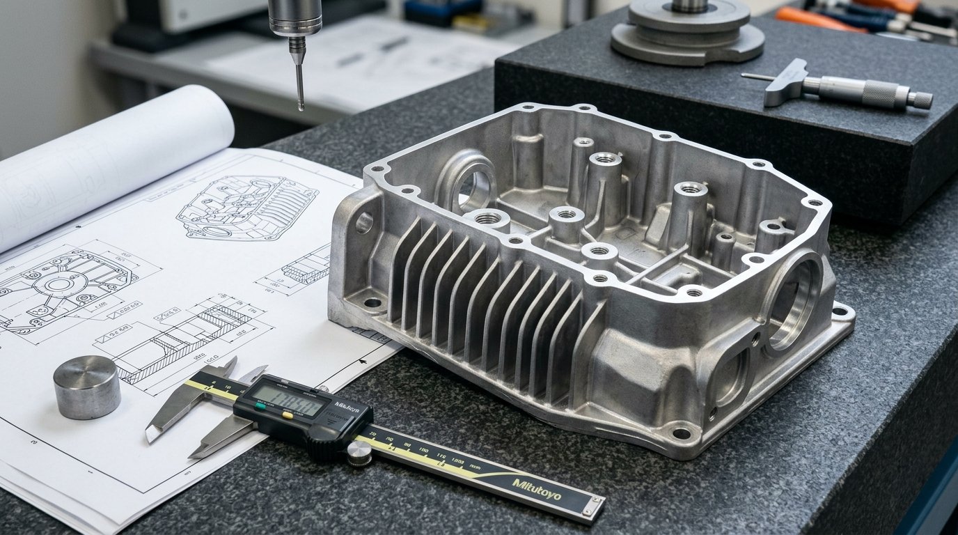
Bore size alone isn’t enough. A bore can be perfectly sized and still be useless if it’s off-axis relative to the opposite bore. Ask for coaxiality and perpendicularity to be measured, typically on a coordinate measuring machine (CMM).
Measure relative to your datums. The inspection report should use the same datum scheme as the drawing, usually the main bore axis and a mounting face. Measurements taken from a convenient edge can hide real problems.
First article, then sampling. Measure every dimension on the first part. After that, sampling critical features on each batch is usually enough, as long as the process doesn’t change.
Check after finishing. If a part is anodized, measure critical fits after the finish, not before.
A useful habit: share how the part assembles. When the inspector knows which faces mate and which bores carry the bearing, the report focuses on what matters.
Lead Times and Batch Planning for Robotics Projects
Robotics schedules are usually driven by the slowest part, and machined aluminum parts are often on the critical path.
Simple brackets and plates can be machined quickly. Complex joint housings with multiple setups and tight bores take longer, and anodizing adds its own time. A first-article inspection on the first batch adds a little more.
Three habits keep projects moving:
- Order long-lead parts first. Housings and complex links should go out as soon as the design is stable, even before brackets.
- Order spares. One or two extra joint housings cost little compared with a stalled build.
- Plan batches around builds. If you’ll build 20 robots over three months, ordering 20 sets at once usually costs less per part and keeps all batches identical.
For a closer look at how quantity changes price, see our guide to aluminum CNC machining cost.
Surface Finishes for Robotic and Automation Parts
| 완료 | Why it’s used in robotics | 다음 사항에 주의하세요 |
| Clear or black Type II anodize | Corrosion protection and clean look on arms and covers | Color varies between 6061 and 7075 |
| III형 경질 아노다이징 | Wear resistance on gripper jaws, guides and sliding faces | Changes dimensions; mask bores and fits |
| Bead blast + anodize | Even matte finish, hides tool marks | Slightly rougher surface |
| Chemical conversion coating | Electrical grounding points, sensor mounts | Less wear resistance |
| 가공된 대로 | Internal parts, fixtures | No corrosion barrier |
The most common finishing problem we see on robot parts is an anodized bearing bore. Anodizing changes the bore size and the coating isn’t meant as a bearing surface. Put “mask bore” or “no anodize in bore” on the drawing.
Design Tips That Lower the Cost of Robot Parts
- Group precision features on one or two faces so they can be machined in the same setup. Features cut in one setup are naturally aligned.
- Use standard hole and thread sizes across all parts in the robot.
- Give pockets generous corner radii so larger, faster tools can be used.
- Define datums that make sense for assembly, usually the main bore axis and a mounting face.
- Avoid deep, narrow slots unless they’re functional.
- Plan threaded inserts for threads that will be assembled and disassembled often. Aluminum threads wear.
- Specify the temper (T6 or T651) on the drawing, not just the alloy.
From Prototype to Production Batches
Robotics projects often move fast from one prototype robot to a pilot run of 10 or 50, then to steady production. The machining approach should evolve with it.
Prototype (1–5 sets). Speed matters most. Expect design changes. Keep tolerances realistic and accept general finishes.
Pilot batch (10–50 sets). Freeze critical features. Ask for a first-article inspection report so you have a measured baseline. Standardize finish specs.
Production (100+ sets). Dedicated fixtures and proven programs bring cycle time and price down. Batch-to-batch consistency now matters more than anything. Keep the same supplier, machines and inspection method where you can.
Switching suppliers at the production stage is possible, but treat it as a new first article. A joint housing that’s 0.02 mm different from the last batch can change how a gearbox runs.
What Commonly Goes Wrong With Machined Robot Parts
These issues cause most rework and delays on robotics projects:
- Bearing bores toleranced as plus-or-minus only, with no coaxiality or perpendicularity callout.
- Anodized bores that end up undersize.
- Over-tightened general tolerances that make every feature expensive.
- Parts that need to fit but come from different suppliers with no shared datum definition.
- Thin, deep-pocketed links that distort after machining.
- Threads in aluminum that strip after repeated maintenance.
Almost all of these are drawing issues, and a supplier’s DFM review before machining usually catches them.
Machining Plus Assembly: Why It Helps Robotics Teams
Many robot sub-assemblies combine machined aluminum parts with bearings, shafts, fasteners, sheet metal covers and molded parts. If each comes from a different supplier, your team becomes the integrator and absorbs every tolerance mismatch.
A supplier that can machine the parts and complete mechanical assembly delivers a tested sub-assembly instead of a box of parts. For pilot and production batches, that can save more engineering time than any per-part price difference.
자주 묻는 질문
What is the best aluminum alloy for robot parts?
6061-T6 suits most robot frames, brackets, mounts and fixtures because it machines and anodizes well at a reasonable cost. 7075-T6 is better for highly loaded links, joint housings and gripper fingers that need more strength. Both alloys have similar stiffness, so stiffness problems need a design change, not an alloy change.
What tolerances do robotic components need?
Most dimensions can use a general tolerance. Bearing bores, mounting faces, pilot diameters and dowel holes need tight control, including coaxiality, flatness and perpendicularity. Bearing seats normally follow the bearing maker’s recommended ISO fit class. Tighten only the features that affect alignment or fit.
Should robot parts be anodized?
Yes, most exposed aluminum robot parts are anodized for corrosion and wear protection. Type II suits covers and arms, while Type III hard anodize suits wear surfaces such as gripper jaws. Bearing bores and precision fits should be masked, because anodizing changes their size.
How can I make machined robot parts lighter?
Pocket low-stress areas, use ribs instead of thick walls, prefer closed box sections for torsion, and keep material around bores and bolt holes. Avoid walls thinner than about 1 mm, which can distort during machining. Large pocket radii keep machining time and cost down.
Is CNC machining suitable for robot production volumes?
Yes. CNC machining handles robot parts from single prototypes to batches of hundreds or more. As volumes grow, dedicated fixtures and proven programs reduce cost per part. For very high volumes, some housings move to die casting with machined critical features, but machining usually covers most robotics programs.
Choosing a Partner for Aluminum CNC Machining for Robotics
The right machining partner understands which features control alignment, holds them consistently batch after batch, and can finish and assemble parts so they arrive ready to build into the robot.
엘리트 몰드 기술 machines aluminum joint housings, brackets, plates and fixtures with in-house finishing and assembly. Send us your drawings for a DFM review and quote at your prototype and production quantities.