 Skip to content
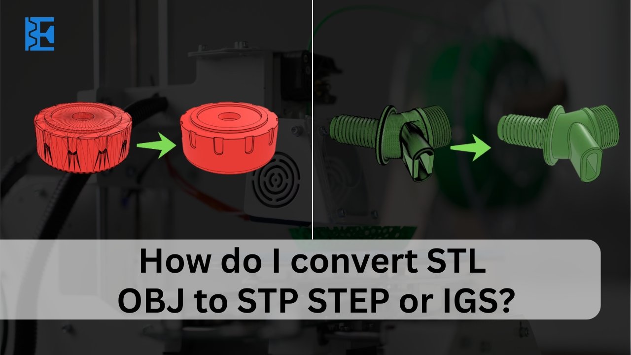
Meta Description: Clear, practical steps for converting STL or OBJ meshes into STEP or IGES solids, with workflows, QA checks, costs, and tips for USA manufacturers.
If you work with prototypes or production parts, you may wonder how do I convert STL OBJ to STP STEP or IGS without losing accuracy or wasting time. This guide explains what each format means, when to remodel versus reverse‑engineer, and how to validate results so CAM, inspection, and sourcing teams can trust the data. You will find step‑by‑step workflows, quality checks, costs, and practical advice for USA buyers, plus an option to engage Elite Mold when deadlines are tight.
Mesh versus CAD in Simple Terms
Before we list the differences, remember that meshes describe surfaces with triangles while CAD models store precise surfaces and edges used by manufacturing and inspection.
- STL and OBJ are meshes that represent shapes using triangles and optional colors or UVs; they lack analytic cylinders, planes, and feature history.
- STEP (.stp, .step) and IGES (.igs, .iges) are B‑rep CAD formats that encode analytic surfaces, edges, tolerances, and assembly structure for downstream engineering.
Why the difference matters: CAM, GD&T, and tolerance drawings expect analytic geometry. Converting triangle soup into clean B‑rep faces is the work, not simply changing a file extension.
Quick Primer on Multi Jet Fusion benefits for context
Understanding benefits helps you match the process to business needs, particularly when balancing speed, strength, and finishing options across prototypes, fixtures, or short-run production programs.
- No support structures are required because powder supports parts, simplifying CAD and post‑processing.
- Mechanical properties are nearly isotropic, which aids consistent function across orientations.
- Batch builds finish quickly, making it suitable for bridge production and functional assemblies.
How do I convert STL OBJ to STP, STEP, or IGS?
Use this guide when deciding an approach because your timeline, process, and accuracy targets should determine whether you remodel features, fit surfaces, or export tessellated.
- Simple prismatic parts: Remodel from dimensions; fastest path to clean, parametric CAD.
- Medium complexity with smooth surfaces: Use auto‑fitting and patch stitching to create NURBS, then a solid.
- Organic shapes: Reverse‑engineer surfaces or export tessellated STEP if CAM accepts triangles.
Core Methods at a Glance
The three methods below reflect common project realities, balancing cost, editability, and accuracy so you can deliver data to machining, molding, or printing teams reliably.
- Direct to tessellated STEP: Import mesh, convert to tessellated body, export STEP; quick for quoting or visualization.
- Feature‑based remodeling: Rebuild with sketches and features; best for machining and future edits.
- Reverse‑engineering with surfaces: Segment mesh, fit planes/cylinders/freeform patches, stitch to watertight B‑rep.
Core Dimensional Rules
Use these baseline numbers as a starting point, then refine with supplier feedback and part size so your expectations match machine capability and inspection outcomes.
- XY tolerance: ±0.2 mm up to 100 mm length, then ±0.2% of the dimension.
- Z tolerance: Comparable to XY; watch tall, thin features for cumulative error.
- Minimum text height and stroke: About 0.5 mm height and 0.3 mm stroke for readability.
- Minimum feature size for emboss/deboss: Around 0.3–0.4 mm in many workflows.
Beyond base tolerances, practical allowances keep assemblies moving without hand fitting; the points below address common hole behavior and strategies for threads and press fits.
- Holes print slightly undersized: Model additional clearance or plan to ream critical bores.
- Threads: Print M6 and larger; tap or use heat‑set inserts for smaller sizes.
- Press fits: Model 0.05–0.10 mm interference and control installation temperature.
Recommended wall Thickness and Feature Sizes
These dimensions reflect common practice across conversion and manufacturing workflows, giving you values that print reliably while leaving room for finishing and machining if required.
- Minimum wall: ~0.8 mm for non‑structural features.
- Preferred wall: 1.2–2.0 mm for load‑bearing housings and brackets.
- Ribs: 60–80% of adjacent wall; keep height‑to‑thickness ≤ 8:1.
- Living hinges: About 0.3 mm in PA 11, oriented in the XY plane.
- Bosses: Diameter ≥ 2× screw major diameter; add generous base fillets.
Build Orientation and Nesting Strategy
Orientation influences measurement results, cosmetics, and cycle time even with isotropic processes; the guidance below helps you protect critical faces while supporting nesting and depowdering.
- Put critical mating faces in XY to leverage better in‑plane accuracy.
- Keep Z height low to reduce build time and heat accumulation.
- Place cosmetic surfaces outward so blasting and dyeing reach them uniformly.
- Align text parallel to the build plane so characters remain crisp after blasting.
Thoughtful nesting raises part count per build and smooths behavior; use these layout practices to improve yield, cosmetic consistency, and powder removal across complex assemblies.
- Maintain at least 2 mm spacing between parts inside the build.
- Distribute mass uniformly to avoid hot spots in dense nests.
- Add engraved part IDs to support QA without stickers that can peel.
Hollow sections, escape holes, and powder removal
Creating hollow volumes reduces material and time, but success depends on clearing powder; the following guidelines make internal cavities printable and easy to clean consistently.
- Provide two or more escape holes on opposite sides; ≥ 6 mm diameter is a safe default.
- Place one hole high and one low to use gravity and airflow.
- Avoid long blind cavities; add vent chimneys if unavoidable.
- Keep internal channels ≥ 2 mm in diameter to clear during blasting.
Designing for strength with ribs, fillets, and lattices
Structural performance improves when you guide stiffness with ribs, soften stress with fillets, and manage weight using lattices; the practices below give results across materials.
- Ribs: Use filleted roots to reduce stress and maintain stiffness without thick walls.
- Fillets: Outer edges radius ≥ 1 mm reduces stair‑stepping; inner corners ≥ 0.8 mm reduce crack initiation.
- Lattices: 15–25% volume fraction balances weight and rigidity; tiny cells risk incomplete fusion.
File prep checklist before conversion
Preparing the file correctly prevents wasted time because broken meshes convert poorly and force fixes later, while good housekeeping lets conversion tools segment features accurately.
- Watertight mesh: No holes, non‑manifold edges, or self‑intersections.
- Units and scale confirmed: Check inches versus millimeters before any operation.
- Reasonable triangle count: Decimate huge scans conservatively to preserve key radii and holes.
- Aligned orientation: Set sensible axes to guide sketches and features.
- Named regions or colors: Tag bosses and flanges to speed surface fitting.
Method 1: Low‑cost and free workflows that work
These steps establish a baseline for any conversion pipeline and help you control changes, keep track of errors, and maintain repeatable results across different parts.
- Import and inspect the mesh; repair holes, flipped faces, and non‑manifold edges.
- Simplify carefully using smart decimation without collapsing small holes or radii.
- Detect primitives such as planes, cylinders, and cones where possible.
- Fit surfaces to primitives and trim or extend boundaries until they meet.
- Stitch surfaces into a watertight solid with an appropriate tolerance.
- Export STEP or IGES and verify edges, faces, and watertightness.
After you complete the basic workflow, use these practical suggestions to keep geometry tidy, hold target tolerances, and avoid surprises during machining, molding, or inspection.
- Lock large planes early so cylinders and blends reference stable datums.
- Create axes from hole centers to stabilize sketches and relationships.
- Use a deviation map to monitor mean and max error while fitting.
Method 2: Professional CAD workflows in production shops
When you need an editable model, this parametric method preserves design intent, eases changes, and aligns with CAM and quality workflows for validating critical features.
- Establish datums from mesh planes to define origin and orientation.
- Extract sections and build constrained sketches for key profiles.
- Create the solid with extrudes, revolves, cuts, holes, and fillets in logical order.
- Add GD&T intent by naming features and capturing relationships.
- Export STEP or IGES with units embedded and a clean feature tree.
Why teams prefer this: You get a true engineering model that edits easily and machines predictably. Future revisions become faster because design intent is captured, not guessed.
Method 3: Reverse‑engineering for complex or organic parts
Some geometries resist sketching, so a surface-based approach becomes practical; the following actions help you control curvature, continuity, and closure while minimizing modeling time.
- Auto‑segment the mesh into planar, cylindrical, and freeform regions.
- Fit NURBS patches and enforce tangency or curvature continuity where needed.
- Tighten stitch tolerance gradually until the solid closes without gaps.
- Validate with a color map and set pass criteria before surfacing begins.
Accuracy Targets and How to Verify Them
Agreeing on measurable targets before conversion prevents disagreements later because everyone sees the same numbers and maps, enabling decisions about readiness for production and inspection.
- Set numeric goals such as ±0.05–0.10 mm for machined parts or ±0.10–0.25 mm for molded housings.
- Use deviation maps to record mean, RMS, and max error against the mesh.
- Spot‑check with calipers on critical dimensions called out on a simple drawing.
- Document assumptions for invisible fillets, drafts, or blends added during modeling.
File Format Choices When the Job is Done
Choosing the right exchange format makes collaboration smoother and avoids import errors; use the guidance below to match your model with your partner’s systems.
- Use STEP for solid models; it is widely supported by CAM and PLM tools.
- Use IGES for surface‑only data or legacy workflows that still prefer it.
- Attach a drawing PDF with key dimensions to speed supplier verification.
Tolerances, GD&T, and manufacturability after conversion
After you obtain a solid, ensure it will manufacture without surprises by applying these adjustments that align geometry with tooling, inspection, and standard feature libraries.
- Add draft angles if you plan to mold; convert zero‑draft mesh walls as needed.
- Normalize fillets to standard radii that cut cleanly and polish consistently.
- Standardize holes to common drill sizes and add counterbores or threads properly.
- Declare datums and basic dimensions so CMM and QA workflows are straightforward.
Conclusion
Converting meshes into reliable CAD is about choosing the right path for your geometry and verifying the result. Simple parts remodel fastest and deliver clean, editable STEP files. Complex or organic shapes usually benefit from reverse‑engineering with surface fitting and a defined tolerance target supported by deviation maps. Keep units consistent, repair the mesh before you start, define inspection goals, and document assumptions.
For USA programs that need speed and certainty, Elite Mold can assess your STL or OBJ and return a production‑ready STEP or IGES with a clear deviation report, so machining, molding, or printing moves forward without surprises.
FAQs
Can I just rename the file extension from STL to STEP?
No. A valid STEP must contain surfaces or solids, not only triangles; you need real geometry conversion.
Which is better for suppliers, STEP or IGES?
STEP is the default for solid models. IGES works for surfaces or legacy systems that need it.
Will automatic tools give me a perfect CAD model?
They can start the job. For production, expect to replace mesh holes with true cylinders and regularize fillets.
How accurate can a conversion be?
With careful remodeling or surfacing, ±0.05–0.20 mm to the mesh is common, subject to scan quality and part size.
Do I need to keep the original mesh?
Yes. Keep it for traceability and to regenerate deviation maps if the model changes later.