A seamless housing drawn from one flat blank costs very little per part, until the design asks the metal to stretch further than one stroke allows. Then the cup tears, the tool needs another station, and the approved quote no longer covers the job. The deep drawing process rewards buyers who check the geometry against the material’s limits before tooling is cut.
This guide covers the process steps, the ratios that limit depth, which sheet grades to order, and how to prevent common defects.
What is the deep drawing process?
Deep drawing is a sheet metal forming method in which a punch pushes a flat blank into a die cavity to make a hollow, closed-bottom part such as a cup, can or box. A blank holder clamps the flange so it feeds in without wrinkling. The shell has no seams, and with several draws its depth can exceed its diameter.
Unlike bending, the metal flows. The shrinking flange sees compressive hoop stress while the wall carries tension.
How the process works, step by step
- Blanking. A blank is cut from coil, sized to the part area plus a trim allowance.
- Clamping. The blank holder presses the blank onto the die face with a controlled force.
- First draw. The punch pulls the flange over the die radius to form a wide, shallow cup.
- Redrawing. Deeper parts are drawn again through smaller tools, by conventional or reverse redrawing.
- Intermediate annealing, if needed. Cold work hardens the metal; heat treatment between draws restores ductility. Our guide to annealing explains how.
- Ironing, where specified. A tight die thins the wall and evens its thickness, as in beverage cans.
- Trimming. The uneven rim is cut off and the part inspected.
Tooling variables that decide success
Concordia University’s sheet metal forming lecture notes list the key variables:
- Clearance. About 1.1 times stock thickness, or roughly 10% more than the sheet.
- Die radius. Too small and the wall tears; too large and the unsupported flange wrinkles.
- Punch radius. Too sharp and the cup splits at the base.
- Binder force. Too low lets the flange wrinkle; too high stops it feeding and the wall tears.
- Lubrication. Drawing compounds cut friction under the flange and over the die radius.
- Punch speed. The right speed depends on material and lubricant.
Which presses suit drawn shells?
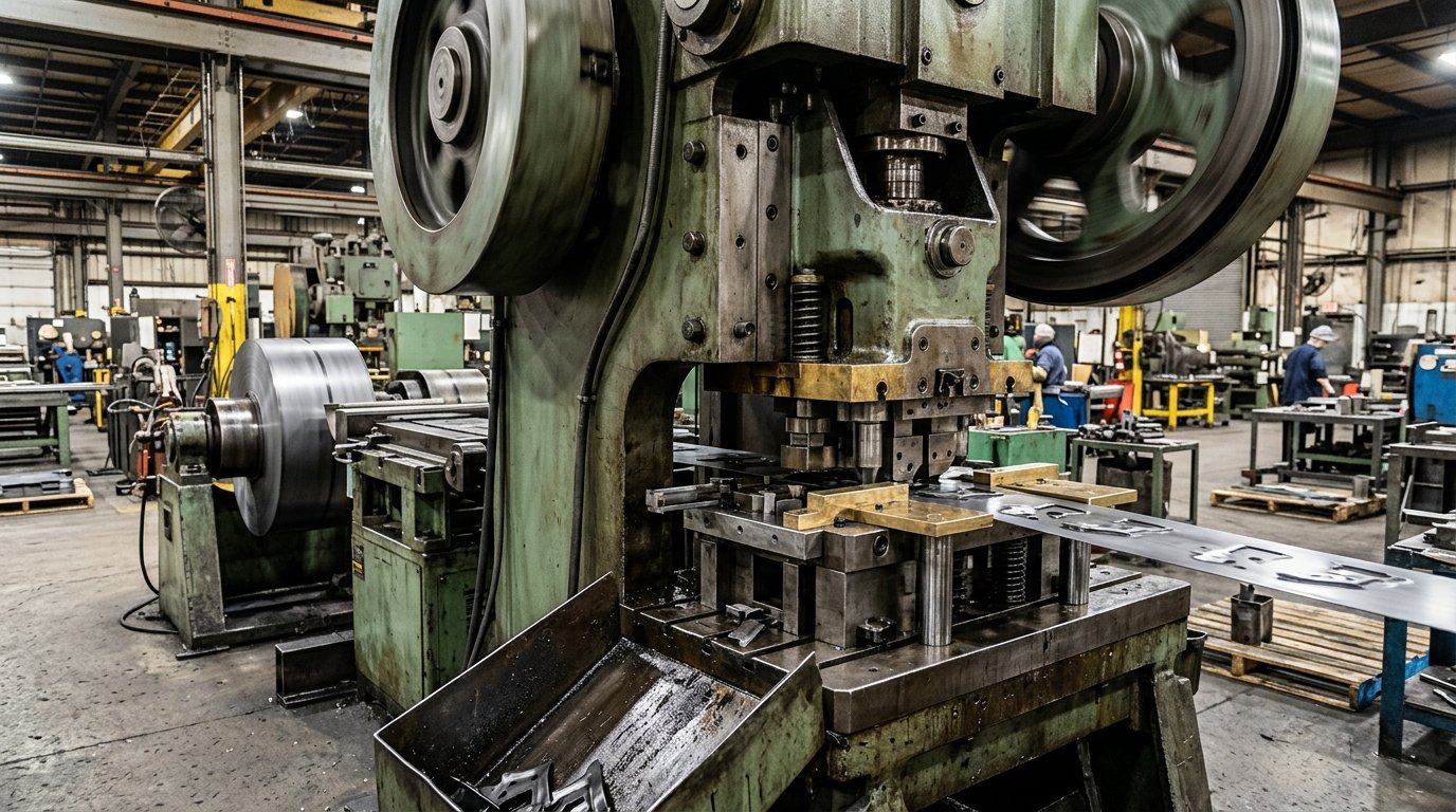
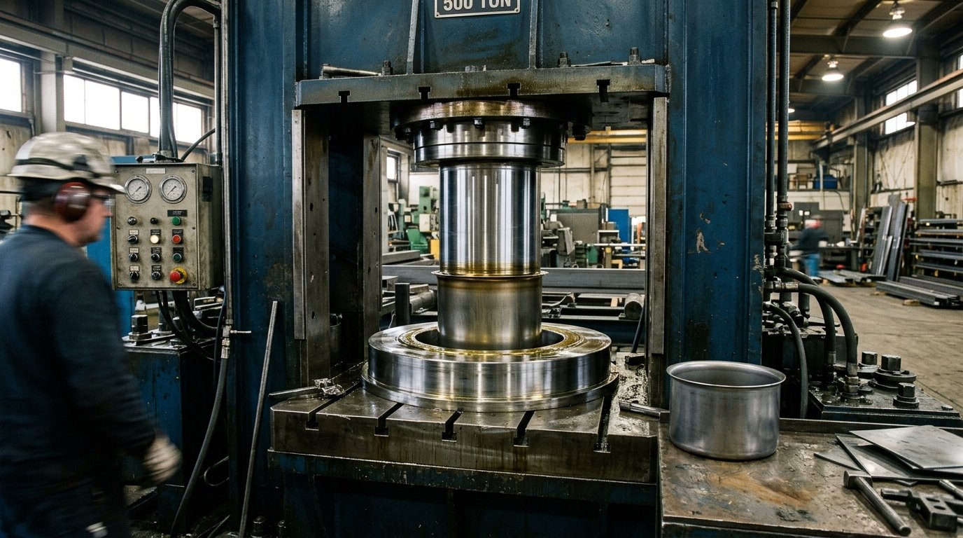
Hydraulic presses give full force through the stroke at controlled speed. Mechanical presses run faster and suit shallow cups in transfer tooling at volume. Servo presses add programmable slide motion at higher cost. For deep parts at modest volume, a hydraulic press with a die cushion is usually the safer choice because force and speed can be tuned at tryout.
What is the drawing ratio, and why does it limit depth?
The drawing ratio (DR) is blank diameter divided by punch diameter, the quickest check on how severe a cylindrical draw will be. The lecture notes pair it with two other measures:
| Measure | Formula | Rough limit for one draw |
| Drawing ratio (DR) | Db / Dp | Below about 2.0 |
| Reduction (r) | (Db − Dp) / Db | Below 0.5 |
| Thickness to diameter | t / Db | Above 1%; lower values wrinkle more easily |
The Mustansiriyah University deep drawing analysis lecture gives the same limits and notes that the real ceiling depends on tool radii, friction, depth and the sheet’s ductility and directionality. Exceed them and the part needs two or more draws, sometimes with annealing between.
These are crude rules. The limiting draw ratio (LDR) is the largest blank a material can draw into a cup without failure, divided by punch diameter. It varies with grade and tooling, so treat 2.0 as a screening number for any drawing operation, not a promise.
Worked example: blank size, DR and force for a cylindrical cup
Take a cup with a 50 mm inside diameter and 40 mm height, drawn from 1.0 mm sheet, ignoring corner radii, thinning and trim:
- Blank diameter. Set blank area equal to part area: Db = √(Dp² + 4·Dp·h) = √(2,500 + 8,000) ≈ 102.5 mm.
- One draw? DR = 102.5 / 50 = 2.05 and r = 0.51. Both exceed the limits, and t/Db is 0.98%. Plan two draws.
- Two draws. First draw to 60 mm (DR 1.71, r 0.41), then redraw from 60 to 50 mm.
- First-draw force. Using F = π·Dp·t·TS·(Db/Dp − 0.7) and an illustrative tensile strength of 300 MPa: F ≈ 57 kN, about 6.4 US tons before tonnage margin.
- Hold-down force. Using Fh = 0.015·Y·π·[Db² − (Dp + 2.2t + 2Rd)²], with yield strength 175 MPa and a 6 mm die radius: about 41 kN.
Those two strengths are the Mustansiriyah lecture’s example values for low-carbon steel. Use mill certificate values for your coil, and add stock for the trim.
Choosing sheet materials
| Material family | Why it is used | Watch for |
| Low-carbon steel (drawing grades) | Ductile, low cost | Needs plating or paint; stretcher strains |
| Stainless steel | Corrosion resistance | Work hardens fast; may need more draws or annealing |
| Aluminum | Light weight | Lower r-value than drawing steel; temper matters |
| Copper and brass | Conductivity, easy forming | Soft surfaces scratch easily |
For stainless, see our 304 vs 316 stainless steel comparison. For aluminum, our guide to reading aluminum alloy and temper designations explains why an alloy number alone is incomplete.
Order drawing steel by designation, not “low-carbon steel”
ASTM A1008/A1008M, the specification for cold-rolled carbon steel sheet, lists commercial steel (CS), drawing steel (DS), deep drawing steel (DDS) and extra deep drawing steel (EDDS) as separate designations. A drawing that says only “CRS” allows commercial grade. Our position: for any shell near the DR limit, name DDS or EDDS on the drawing and ask for mill certs. Finding a grade substitution at tryout costs far more than specifying it up front.
Check the r-value
The plastic strain ratio, or r-value (unlike reduction r), measures how well a sheet resists thinning. ASTM E517 is the test method for r in sheet intended for deep drawing. A higher average r raises the LDR. Typical ranges from the Concordia notes, which vary with processing, so check your coil:
| Sheet | Typical average r |
| Cold-rolled aluminum-killed steel | 1.4–1.8 |
| Cold-rolled rimmed steel | 1.0–1.4 |
| Stainless steels | 0.9–1.2 |
| Hot-rolled steel | 0.8–1.0 |
| Copper and brass | 0.6–0.9 |
| Aluminum alloys | 0.6–0.8 |
Common deep drawing defects and how to prevent them
| Defect | What you see | Usual cause | Typical fix |
| Flange wrinkling | Radial ridges in the flange | Binder force too low, low t/Db | Raise binder force, add draw beads |
| Wall wrinkling | Ridges drawn into the cup wall | Wrinkled flange pulled into the die | Fix the flange first; review die radius |
| Tearing | Crack near the cup base | DR too high, sharp punch radius, excess binder force | Add a draw, open radii, lubricate |
| Earing | Wavy top edge with 4, 6 or 8 peaks | Planar anisotropy in the sheet | Order low-anisotropy sheet; add trim allowance |
| Scratches and galling | Score lines on the wall | Rough tooling, poor lubrication | Polish tooling, improve lubricant |
| Orange peel | Rough, pebbled surface | Coarse grain size | Specify finer-grain sheet for cosmetic parts |
| Stretcher strains | Irregular bands on low-carbon steel | Yield-point elongation (Lüders bands) | Sheet temper rolled 0.5–1.5% in thickness |
Most online guides skip the last two, yet they reject cosmetic parts. Ears form because r differs with direction; when that difference is zero, no ears form.
What commonly goes wrong in production
Most problems appear at tryouts, not in CAD. A drawn cup that simulated cleanly tears on the first hit because the coil differs from the grade modeled. Each fix means pulling the die, reworking a radius and resampling.
Buyers who approve a drawing before the supplier checks DR and grade often pay for an extra station later. Finite element simulation reduces that risk only as far as its material data is accurate.
Advantages and limitations of deep drawing
Advantages: seamless, leak-tight shells; low piece cost at volume; good material use; stiff parts from thin sheet.
Limitations: tooling and tryout time before the first good part; extra stations for deep parts; walls thin near the base and thicken near the rim unless ironed.
When is deep drawing the right choice?
Typical deep drawn parts include battery and sensor cans, sinks, cookware, filter housings, automotive shells, medical housings and artillery shell cases.
For a few prototypes, spinning, hydroforming or machining is usually cheaper because they need little dedicated tooling. At volume, drawing wins on piece price. The crossover depends on size, depth and material, so quote both routes.
What to put on the drawing and RFQ
- Material by designation (for example DDS or EDDS), thickness and temper
- Critical diameters and depth, with datums and tolerances
- Minimum wall thickness at the base radius, where thinning is worst
- Trim allowance or finished-edge requirement, since ears must be cut off
- Cosmetic surfaces, so orange peel and stretcher strains are ruled out early
- Annual volume and program life, which decide draw count and press type
Frequently asked questions
What is the difference between deep drawing and stamping?
Stamping is the broad family of press operations: blanking, piercing, bending, coining and drawing. Deep drawing is one of them, pulling the sheet into a hollow shell rather than cutting or bending it. It needs a punch, die and blank holder, and deep parts often need several stations or presses.
What is a good limiting draw ratio?
University lecture notes give about 2.0 as a rough ceiling for one draw of a cylindrical cup, with reduction below 0.5. The real value depends on material grade, r-value, die and punch radii, lubrication and depth. Treat 2.0 as a screening number, and ask your supplier to confirm it with their own tryout data.
How do you prevent tearing and wrinkling?
Balance the binder force: too little lets the flange wrinkle, too much stops it feeding and the wall tears. Keep die and punch radii generous, lubricate the flange and die radius, and keep the drawing ratio within limits. If the part is too deep, add a redraw rather than forcing one stroke.
Can deep drawing be used for prototypes or small runs?
It can, but dedicated tooling and tryout make small runs expensive per part. Spinning, hydroforming or machining usually cost less for a few pieces. A common route is prototypes by another method, then drawing tools once the design is stable and volumes justify the investment in dies and tryout.
What causes earing in a drawn cup?
Earing comes from planar anisotropy: the sheet stretches differently in different directions relative to rolling. The cup rim then rises in four, six or eight peaks. Buyers limit it by ordering sheet with low planar anisotropy and by leaving enough trim allowance so the uneven edge can be cut off cleanly.
Planning a deep drawing process for your next part
Check the geometry before asking for prices. Calculate the blank, DR and t/Db, name the steel designation, and mark where wall thickness matters. If the numbers say two draws, budget for each deep draw station. A supplier review before dies are built saves more than a lower piece price.
Elite Mold Tech offers deep drawing as part of its metal stamping service. Send drawings through the request a quote form, or see every service on the Elite Mold Tech homepage.