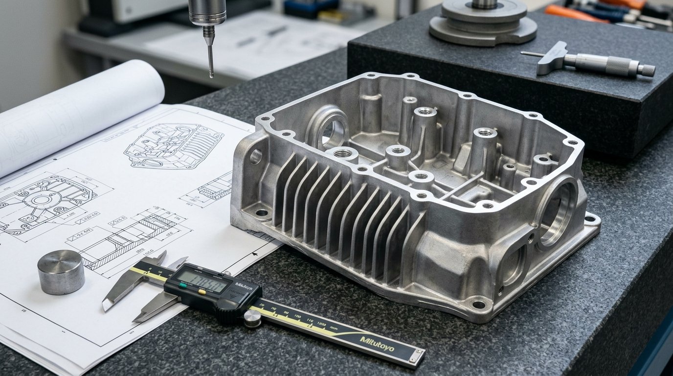
A drawing that borrows its rules from a machined part usually survives the quote and fails in the die. A zero-draft wall drags on ejection, a thick boss comes out porous, and a sharp inside corner starts a crack in the die steel. The die casting design guidelines below catch those problems while they are a CAD edit, not a weld repair on hardened tooling.
This design guide covers walls, draft, fillets, ribs, bosses, the parting line and porosity, using figures from the North American Die Casting Association (NADCA).
What makes a part easy to die cast?
A die cast part is easy to produce when molten metal fills every section before it freezes, the casting can shrink and eject without dragging, and the die has no thin or sharp steel that cracks early. In practice that means thin uniform walls, draft on every surface parallel to die opening, generous fillets and a simple parting line.
Die cast design rules at a glance
| Feature | Guideline | Source |
| Average wall | 0.040 to 0.200 in (1.0 to 5.1 mm), depending on alloy, size and application | NADCA PSS 2021, 4A |
| Thin wall | Down to 0.020 in (0.5 mm) on smaller castings, with die caster consultation | NADCA PSS 2021, 4A |
| Wall around metal savers | Within ±10% of the most typical wall section | NADCA PSS 2021, 4A |
| Draft | 1 to 2 degrees of taper; inside walls twice the outside value | NADCA PSS 2021, S/P-4A-7 |
| Fillet at a tee junction | R = T to 1.25T, where T is the thinnest wall at the junction | NADCA G-6-2 |
| Minimum fillet | Consider 0.06 in (1.5 mm) as a minimum | NADCA PSS 2021, 4A |
| Sharp corners | Required at the parting line and die block intersections; radius elsewhere | NADCA G-6-3 |
Treat these design rules as starting points; NADCA itself calls its dimensions reference values.
Die casting wall thickness: thin, uniform, with gradual transitions
Die casting wall thickness has no hard maximum or minimum; NADCA’s typical range depends on alloy, part size and flow length. Its design site asks for consistency: uniform walls, with blended rather than stepped transitions. Go too thin for the flow length and metal freezes early, leaving cold shuts.
The common mistake in casting design is to thicken a wall to make it stronger. The center of a heavy section is the last metal to freeze and is where porosity collects, so a thick wall often performs worse than a thinner one with ribs. NADCA’s rib guideline says as much: ribs often add more strength than solid material, because solid material carries porosity.
We recommend this order: when a die cast part needs strength, add ribs or a metal saver before you add wall, and keep the remaining wall within about 10% of the typical section.
How much draft angle for die casting is enough?
NADCA’s design guidance on draft explains why the draft angle for die casting changes from feature to feature. Metal shrinks onto the steel forming inside walls and holes, so those need the most draft. It shrinks away from outside walls, so they need the least.
NADCA’s 2021 standards recommend 1 to 2 degrees and list what moves the number:
- Depth. Deeper features need a smaller draft angle than shallow ones.
- Alloy. Aluminum needs more than zinc; aluminum, magnesium and copper are similar.
- Elongation. Structural aluminum with higher as-cast elongation may need less.
- Inside versus outside. Inside walls get twice the draft of outside walls.
Cast lettering and logos are reviewed individually.
What a draft angle means in steel
An angle on a drawing becomes an offset on the part. Using NADCA’s example angles, offset = depth x tan(angle):
| Feature depth | Draft angle | Offset at the top of the wall |
| 0.1 in (2.5 mm) | 2° | 0.0035 in (0.09 mm) |
| 1.0 in (25 mm) | 1.5° | 0.026 in (0.67 mm) |
| 5.0 in (127 mm) | 1° | 0.087 in (2.2 mm) |
The last row is where a die cast design goes wrong. On a 5 in deep wall, 1 degree moves the face almost 0.09 in, and because inside faces take twice the draft of outside faces, a wall drawn at 0.10 in changes thickness along its depth. Apply draft in the model before you check walls, clearances and machining stock.
Fillets and corners sized from the wall
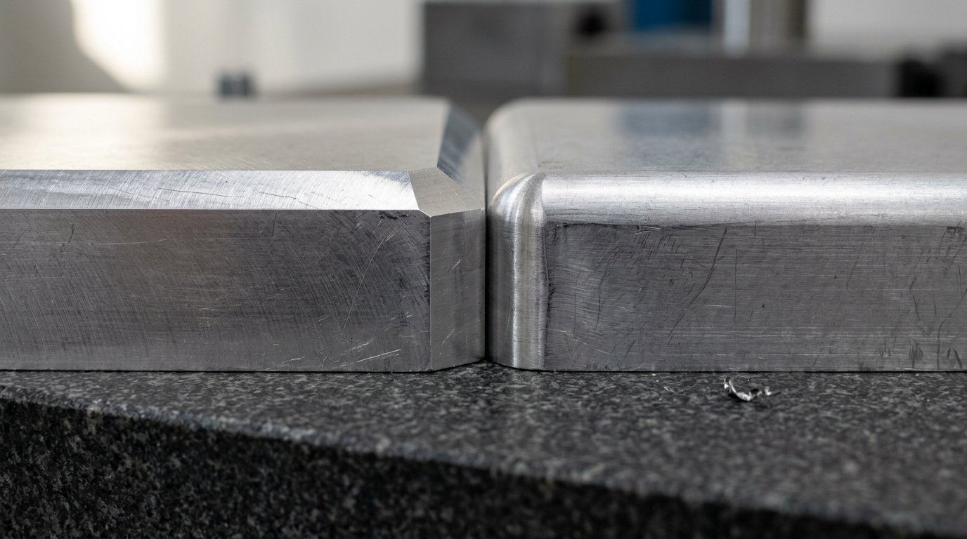
A fillet is the curved junction of two surfaces that would otherwise meet at a sharp corner. NADCA’s G-6-2 guideline sizes it from the wall rather than giving one number:
- Tee junction: fillet radius of T to 1.25T, where T is the thinnest wall at the junction.
- L-shaped corner of uniform wall: inside radius equal to T and outside radius equal to the inside radius plus T, keeping the wall constant around the bend.
- Minimum: NADCA suggests considering 0.06 in (1.5 mm) as a minimum radius at transitions.
Bigger is not always better. A fillet radius that is too large leaves a heavy mass at the junction, which NADCA flags as “not conducive to sound metal”. Deep pockets need larger fillets than shallow features, and fillets normal to the parting line take the draft of the surface they join.
One corner stays sharp. Squared external corners are required at the parting line and where die blocks intersect. Everywhere else, radius corners to extend die life and reduce nicked edges.
Ribs and bosses
Ribs add stiffness without adding wall and give molten metal a flow path. NADCA’s rib design notes add two cautions. Give every rib fillets and draft. And use ribs only where needed, because unnecessary ribs add die cost. The same page suggests odd numbers of ribs.
What commonly goes wrong is rib spacing. Closely spaced ribs leave thin blades of steel between them in the die. Those blades wear and crack, sending the die into maintenance.
Die caster websites quote rib thickness ratios from half the wall to the full wall. They conflict and none traces to a primary source, so we give no ratio. Agree rib thickness with your caster based on alloy, flow length and gate position.
Bosses follow the same die casting rules. Core a hole through the center of a boss to keep its wall uniform, and tie it to nearby walls with ribs and fillets so metal can feed it. For larger castings, NADCA adds two numbers: use ribs once boss height exceeds boss diameter, and leave at least 0.25 in between adjacent bosses to limit porosity.
Where should the parting line go?
The parting line is where the cover half and ejector half of the die meet. NADCA’s parting line guidance recommends fixing it early, with designer and caster working together:
- Gates, overflows and vents attach there, and the trim die removes them.
- Flash forms at the parting line and adds to any dimension measured across it.
- Critical dimensions held within one die half vary less than dimensions that cross the line.
- Cosmetic surfaces normally go on the cover side.
- Most geometry in the ejector half keeps the casting from sticking in the cover half.
A stepped parting line costs more to build and trim. Undercuts cost more again, since they need slides or side cores. Our position: simplify the parting line first, then decide whether an undercut justifies a slide or a machining step.
Ejector pins and witness marks
Ejector pins push the casting off the ejector half and leave round witness marks. For larger castings, NADCA calls for a pin diameter of at least 0.38 in (10 mm) in non-functional areas, pads from 0.06 in raised to 0.03 in depressed, and pin flash up to 0.04 in on as-cast surfaces. Mark sealing, cosmetic and datum faces where pins must not land, and leave ribs and bosses to push on.
Can you reuse plastic part design rules for die casting?
Only partly. Plastic design rules center on sink marks, warp and cooling time. Die casting rules center on metal flow, shrinkage onto die steel, porosity and die life. The details differ:
- Die casting draft is asymmetric: twice as much on inside walls as outside.
- Fillets are sized from the thinnest wall at the junction, and oversized fillets cause porosity.
- A sharp corner is mandatory at the parting line.
- Thicker metal is often weaker, not stronger.
Converting a molded part? Compare our draft angle guide for plastic parts and wall thickness rules for molded parts. For basics, see our overview of die casting process, materials and characteristics.
Designing against porosity and excess machining
No high pressure die casting is completely free of gas porosity or shrinkage porosity. Casting design decides where it ends up. Die castings have a dense, fine-grained skin near the surface, so every extra cut moves closer to the more porous core. NADCA’s large-casting guidance limits machining stock to 0.06 in (1.5 mm) and recommends stepped cores to reduce heavy sections.
For cored holes in larger castings, NADCA suggests a 0.25 in minimum diameter, with length-to-diameter ratios up to 4:1 below 0.50 in diameter and 10:1 above. Holes and windows need more draft than any other feature.
Specify porosity limits only on faces that need them, such as sealing grooves and pressure-tight bores. A blanket requirement raises cost without improving function. If the part will be plated or painted, check finish needs early with our guide to die casting surface finish options.
Putting draft and radii on the drawing
Specifying draft on every feature is not common practice. NADCA recommends a general note with exceptions called out. Its example: an aluminum casting with most features at least 1.0 in deep can carry a note of 2° minimum inside and 1° minimum outside. Handle radii the same way, with one general fillet note; it keeps the drawing readable.
Ask which edition of the NADCA Product Specification Standards your caster quotes against. The 2015 edition calculated draft from a formula with alloy constants; the 2021 edition gives a 1 to 2 degree range. Precision tolerances cost more than standard ones, so use them only where needed.
For larger castings, NADCA’s design guidelines add more checks: keep the range of wall thickness within 2x the thinnest wall, use 0.14 in (3.5 mm) as a general wall and fillet radius, and treat 0.060 in (1.5 mm) as the minimum fillet and 0.020 in (0.5 mm) as the minimum corner radius.
Frequently asked questions
What is the minimum wall thickness for die casting?
NADCA gives typical average walls of 0.040 to 0.200 in (1.0 to 5.1 mm), depending on alloy, part size and application. Smaller castings can reach 0.020 in (0.5 mm) with die caster consultation. Treat these as reference values and confirm the limit for your alloy and flow length with the caster.
How much draft does a die casting need?
NADCA’s 2021 standards recommend 1 to 2 degrees, with twice as much draft on inside walls as outside walls. Aluminum needs more than zinc, deeper features need a smaller angle, and holes need the most. NADCA’s example note for aluminum parts with features at least 1 in deep is 2 degrees inside, 1 degree outside.
How do you reduce porosity through part design?
Keep walls thin and uniform, core out heavy sections with metal savers, and use ribs instead of thick walls for strength. Avoid oversized fillets that create heavy junctions, keep bosses apart, and minimize machining stock so cuts stay in the dense surface skin rather than the porous core.
Can a die cast part have sharp corners?
Yes, but only in specific places. NADCA guidelines require squared external corners at the parting line and where die blocks meet. Elsewhere, corners and junctions should carry fillets or radii to spread stress in the casting and the die, improve metal flow and extend die life.
Where should ejector pins go on a die cast part?
Pins should push on sturdy features such as ribs, bosses and thick flanges, spaced for even ejection. Keep them off sealing, cosmetic and datum faces, since each pin leaves a witness mark and can leave flash. Mark those exclusion zones on the drawing before the die design starts.
Applying these die casting design guidelines before tooling
Costly die changes usually trace back to decisions nobody wrote down. Before the die is designed, settle and send:
- A 3D model with draft already applied, and a drawing with general draft and fillet notes
- The preferred parting line, cosmetic faces and critical dimensions, ideally within one die half
- Faces where pins may not land, and faces that will be machined
- Zones with porosity or pressure-tightness requirements
- Alloy (for example A380 aluminum or a zinc alloy), annual volume and finish; our aluminum vs zinc die casting comparison helps with alloy choice
Then ask the caster to review the die cast design against the standard they work to. A change at that stage costs an engineering hour. After the die is hardened, the same change costs welding, re-machining and a new tryout.
Elite Mold Tech offers die casting with design review before tooling, alongside machining, finishing and assembly. See the full range of manufacturing services on the Elite Mold Tech homepage.