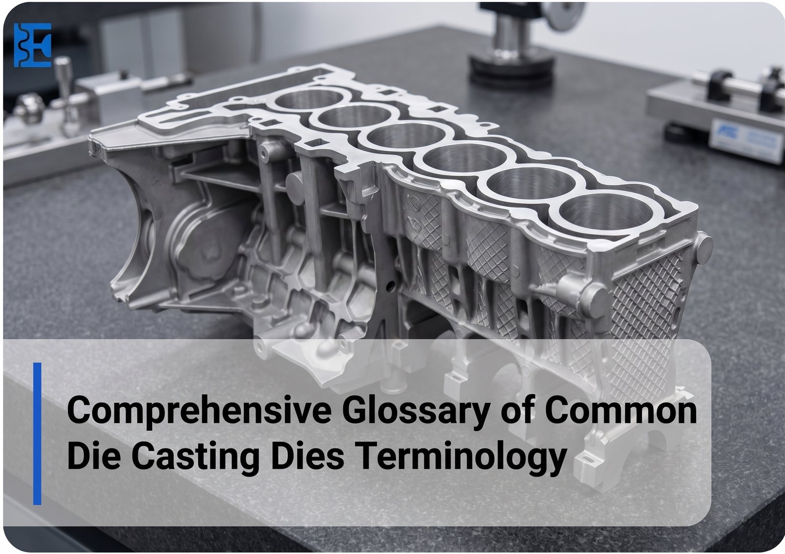
What do terms such as fixed die, moving die, cavity, runner, gate, ejector pin, draft, overflow well, slide, and sprue bush mean in die casting? How do these die casting terms relate to metal flow, tool movement, part ejection, cycle stability, and final casting quality? Which terms should engineers, buyers, product designers, and manufacturing teams know before reviewing a die or starting a die casting project?
Die casting terminology describes the parts, features, forces, movements, and flow elements used in a die casting tool and machine. The most important terms include fixed die, moving die, cavity, core, parting line, sprue, runner, gate, vent, overflow well, ejector system, draft, slide, die insert, clamping force, and injection pressure. Knowing these terms makes design reviews clearer and reduces misunderstandings during quoting, tooling, sampling, troubleshooting, and production.
Why Die Casting Terminology Matters
Die casting forms metal parts by forcing molten metal into a reusable steel die under pressure. Elite Mold Tech describes hot-chamber and cold-chamber methods as common process categories and supports aluminum, zinc, and magnesium die casting for production parts.
For a buyer or engineer, these terms are practical rather than academic. A gate controls where metal enters the cavity, a vent allows trapped air to escape, draft supports part release, and a slide creates side features that cannot release in the main opening direction. Consistent terminology helps tooling engineers, machine operators, quality teams, and customers discuss the same feature without confusion.
For projects that require tooling and production support, Elite Mold Tech’s die casting services cover custom die casting molds, aluminum, zinc, and magnesium alloys, secondary operations, and high-volume production.
Core Die Casting Die Terms
A die casting die is the complete metal-forming tool used to shape molten metal into a repeatable part. It contains the forming surfaces and the systems needed to fill, cool, open, and eject the casting.
The fixed die, sometimes called the fixed half or A-side, stays on the stationary platen. The moving die, or B-side, opens with the movable platen and commonly carries the ejection system. The cavity is the negative space that forms the outside shape of the casting, while a core creates internal holes, recesses, or other internal geometry.
The parting line is where the two die halves meet. Its position can affect flash, appearance, tool construction, and part release. A die insert is a separate precision section installed in the die body so a local feature can be machined, repaired, or replaced more efficiently.
| Term | Simple Definition | Why It Matters |
| Die casting die | Complete forming tool | Controls part shape and repeatability |
| Fixed die | Stationary die half | Supports one side of the cavity |
| Moving die | Opening die half | Commonly carries ejection components |
| Cavity | Space that forms the part exterior | Defines primary geometry |
| Core | Feature forming internal geometry | Creates holes and recesses |
| Parting line | Meeting line of die halves | Affects flash and release |
| Die insert | Replaceable local tooling section | Helps maintenance and feature control |
| Draft | Small taper on release surfaces | Makes ejection easier |
Sprue, Runner, Gate, Vent, and Overflow
The metal-flow system controls how molten alloy reaches and fills the cavity. These terms are among the most important in everyday die casting discussions.
A sprue is an entry passage that directs metal toward the runner system. The runner carries molten metal toward one or more gates. The gate is the final restricted opening through which the metal enters the cavity. Its location and size influence filling behavior and how the feed system is removed after casting.
An overflow well is positioned beyond selected cavity areas to receive excess or early-flow metal and support stable filling. An air vent provides a path for displaced air and gases to leave the cavity as metal enters. Poor venting or unsuitable flow design can contribute to casting quality problems.
Elite Mold Tech’s guide to die casting process, materials, and characteristics gives additional context on process types, common alloys, and typical die casting defects.
Injection, Clamping, and Machine Terms
Injection pressure is the pressure used to force molten metal into the die. Injection speed describes the movement of the injection plunger or mechanism, while filling velocity refers to how quickly metal advances through the die flow path.
Clamping force, sometimes called locking force, keeps the die halves closed against pressure during filling. Projected area is the area of the cavity and related features viewed perpendicular to the clamping direction. Tool and process engineers consider these factors when matching a die to a suitable machine.
Ejection, Slides, and Side Actions
After the alloy solidifies, the die opens and the casting must be removed. An ejector pin pushes against the solid part, while an ejector plate moves a group of pins together. Return or reset mechanisms bring the system back into position before the next cycle.
Stripper distance describes the opening or movement needed to create enough room for the casting and feed system to be removed. Draft works closely with ejection because a properly tapered surface releases with less resistance.
Parts with side holes, undercuts, or cross-features may require a slide. A slide moves sideways or at an angle relative to the main opening direction. A core slide carries a core-forming feature. An angle pin converts die opening movement into slide movement, while a wedge block supports or locks the slide when the die closes.
Common Die Casting Dies Terminology for Tool Review
Understanding individual terms is useful, but engineers also need to know what each feature means during an actual tooling review. A correctly designed feature must support metal flow, tool movement, part release, and repeatable production at the same time.
| Tool Review Term | What Engineers Usually Check |
| Draft angle | Enough taper for clean release |
| Gate | Position, size, filling effect, and removal |
| Runner | Controlled and balanced metal flow |
| Vent | Clear escape path for air and gas |
| Overflow | Location near selected last-fill areas |
| Slide | Travel, guidance, locking, and clearance |
| Ejector pin | Position, force distribution, and marks |
| Insert | Fit, wear, repair access, and replacement |
| Parting line | Sealing, flash risk, and appearance |
A tooling review should consider these features as one connected system. Changing the gate, for example, may affect filling direction and trimming, while changing a slide may influence tool size, ejection clearance, and cycle sequence.
Die Casting Materials and Process Vocabulary
Tool terminology makes more sense when connected to the casting alloy. Elite Mold Tech lists aluminum, zinc, and magnesium among its die casting materials. Different alloys affect melting conditions, fill behavior, cycle design, and tooling decisions.
Zinc is commonly associated with hot-chamber die casting. Elite Mold Tech’s zinc die casting guide describes a cycle that includes mold preparation, injection, cooling and ejection, and trimming. Aluminum is commonly handled through cold-chamber die casting, where molten metal is transferred into the injection chamber before being forced into the die.
These differences explain why the same tooling discussion may involve different machine terms depending on the selected alloy. Designers should therefore confirm both material and production method before finalizing die structure, feed-system details, cooling requirements, and machine compatibility.
Fixed Inserts, Moving Inserts, and Movable Cores
A fixed-half insert is installed on the stationary side of the die and forms part of the casting surface. A moving-half insert performs a similar function on the moving side.
A movable core changes position during the casting cycle. It is commonly used when the component contains a hole, recess, or undercut that would prevent straight ejection.
A movable insert can also form a feature that must move before the casting is released. These components make more complicated geometries possible, but they add mechanical movement to the tool. Their travel, locking position, wear surfaces, and clearance must therefore be considered during tooling design.
A split is a tooling arrangement in which several separate pieces combine to form a core or cavity. Splits can be useful when the geometry would be difficult to manufacture, assemble, or release as one solid component.
Sprue Bush and Metal Distribution Features
The sprue bush forms part of the metal entry system and provides a controlled path into the die. From there, molten metal moves into the runner network and eventually reaches the gates.
A sprue spreader redirects or distributes incoming metal so it can transition smoothly into the feed system. Some dies also use flow-directing features to guide molten alloy toward selected areas of the cavity.
These features may appear small compared with the main cavity, but they can strongly influence how evenly the metal reaches different regions of the part. Their design should be considered together with gate position, runner balance, venting, overflow areas, and cavity geometry.
Why Draft Is Important in Die Casting Dies
Draft is a small angle added to surfaces that run in the direction of tool opening. Without sufficient draft, the solidified casting can grip the cavity or core as the die opens.
The correct amount of draft depends on the feature depth, alloy, surface condition, geometry, and whether the surface is internal or external. A deeper wall typically requires more consideration than a very shallow feature.
Draft should be included early in product design rather than added after the tooling is complete. This helps protect cosmetic surfaces, reduces resistance during ejection, and gives ejector pins a better chance of releasing the part without excessive force.
How Terminology Helps Prevent Die Casting Problems
Many casting problems are easier to discuss when the team uses exact tooling language. Instead of saying that metal is “not filling correctly,” an engineer can identify whether the concern involves the gate, runner, vent, overflow, injection conditions, or cavity geometry.
If flash appears, the team can review the parting line, clamping conditions, die wear, and local tool fit. If an ejection mark appears, ejector pin position, draft, cooling, and release resistance can be reviewed.
This is one reason a technical glossary has practical value. It turns broad observations into specific tooling discussions, making root-cause analysis more focused.
How to Use This Glossary During a Project
During quotation, use these terms to clarify part geometry, alloy, projected area, draft, side actions, and expected tool size. During design review, focus on cavity layout, runner and gate design, vents, overflow locations, inserts, slides, and ejection. During sampling, the same vocabulary helps teams document flash, filling problems, ejection marks, dimensional variation, and tool corrections.
Terminology becomes especially valuable when a drawing revision affects the die. Instead of saying that a feature needs to “move,” a team can specify whether the change affects the cavity insert, movable core, slide travel, gate, runner, or ejector layout. That level of precision reduces ambiguity and speeds up communication between design and manufacturing teams.
Conclusion
A clear grasp of die casting dies terminology makes technical communication more accurate from early design through full production. Terms such as cavity, core, parting line, runner, gate, vent, overflow, slide, insert, draft, injection pressure, clamping force, and ejector pin describe connected parts of one manufacturing system.
For engineers and buyers, the goal is not simply to memorize vocabulary. It is to connect each term to metal flow, tool movement, ejection, maintenance, machine setup, and final part quality. When design and manufacturing teams use the same terminology, die casting projects become easier to specify, review, troubleshoot, and scale.
What is the difference between a die and a cavity?
A die is the complete tooling assembly used in the die casting process, while the cavity is the shaped space inside that die. The cavity forms the external shape of the final casting. A single die may contain one or multiple cavities depending on production requirements.
What is the difference between a runner and a gate?
A runner is the channel that carries molten metal from the entry point toward the casting cavity. The gate is the smaller final opening through which the metal actually enters the cavity. Both features play an important role in controlling metal flow and filling quality.
Why is draft needed in die casting?
Draft is a slight angle added to vertical surfaces so the finished casting can release from the die more easily. Without enough draft, the part may stick to the cavity or core during ejection. Proper draft also helps reduce surface damage and excessive ejector force.
What does a slide do in a die casting die?
A slide is a movable tooling component used to create side holes, undercuts, grooves, or other features that cannot be released in the main die-opening direction. It moves sideways before the casting is ejected. Slides make more complex part geometries possible in die casting.
What is an overflow well?
An overflow well is an extra area connected to the casting cavity that receives excess or early-flow metal during filling. It can help move trapped air, oxides, and colder metal away from important part areas. Proper overflow design can support more consistent casting quality.
What is the purpose of an ejector pin?
An ejector pin pushes the solidified casting away from the moving half of the die after the tool opens. Multiple ejector pins are usually positioned across the part to distribute the ejection force. Correct placement helps reduce deformation, sticking, and visible ejector marks.
About the Author:
Alex Morgan specializes in technical content for precision manufacturing, with a focus on CNC machining, injection molding, die casting, 3D printing, sheet metal fabrication, and custom mold manufacturing. With more than a decade of experience in B2B manufacturing content and SEO, he creates technically accurate content designed for engineers, product developers, procurement teams, and manufacturing decision-makers. His work helps global manufacturers clearly communicate complex production capabilities, material options, tolerances, tooling processes, and quality standards to customers across the US, Europe, and Asia-Pacific. He writes for manufacturing companies where technical expertise, precision, and reliability matter.