By Phil Huang, Elite Mold Tech. Updated October 31, 2026.
Standard aluminum CNC machining tolerances at Elite Mold Tech are ±0.005 in (±0.127 mm). On critical features, we hold down to ±0.001 in (±0.025 mm) when you send a 2D drawing with GD&T. The right limit for your part is the loosest one that still works, because every step tighter adds inspection time and cost. This guide explains what each level means and how to set it.
The numbers below come from our own capability table. They are what the shop quotes and inspects against on US orders.
Key takeaways
- Standard tolerance is ±0.005 in (±0.127 mm). Tight tolerance is ±0.001 in (±0.025 mm) on request.
- Typical hole tolerance is ±0.002 in (±0.05 mm), and minimum wall thickness is 0.75 mm.
- Tighten only the features that mate, seal, or move. Leave everything else on the general tolerance.
- Temperature, finish, and part size change what you measure, not just how you cut.
- A 2D drawing with GD&T gives the fastest and most accurate quote.
What tolerances can CNC machining hold on aluminum?
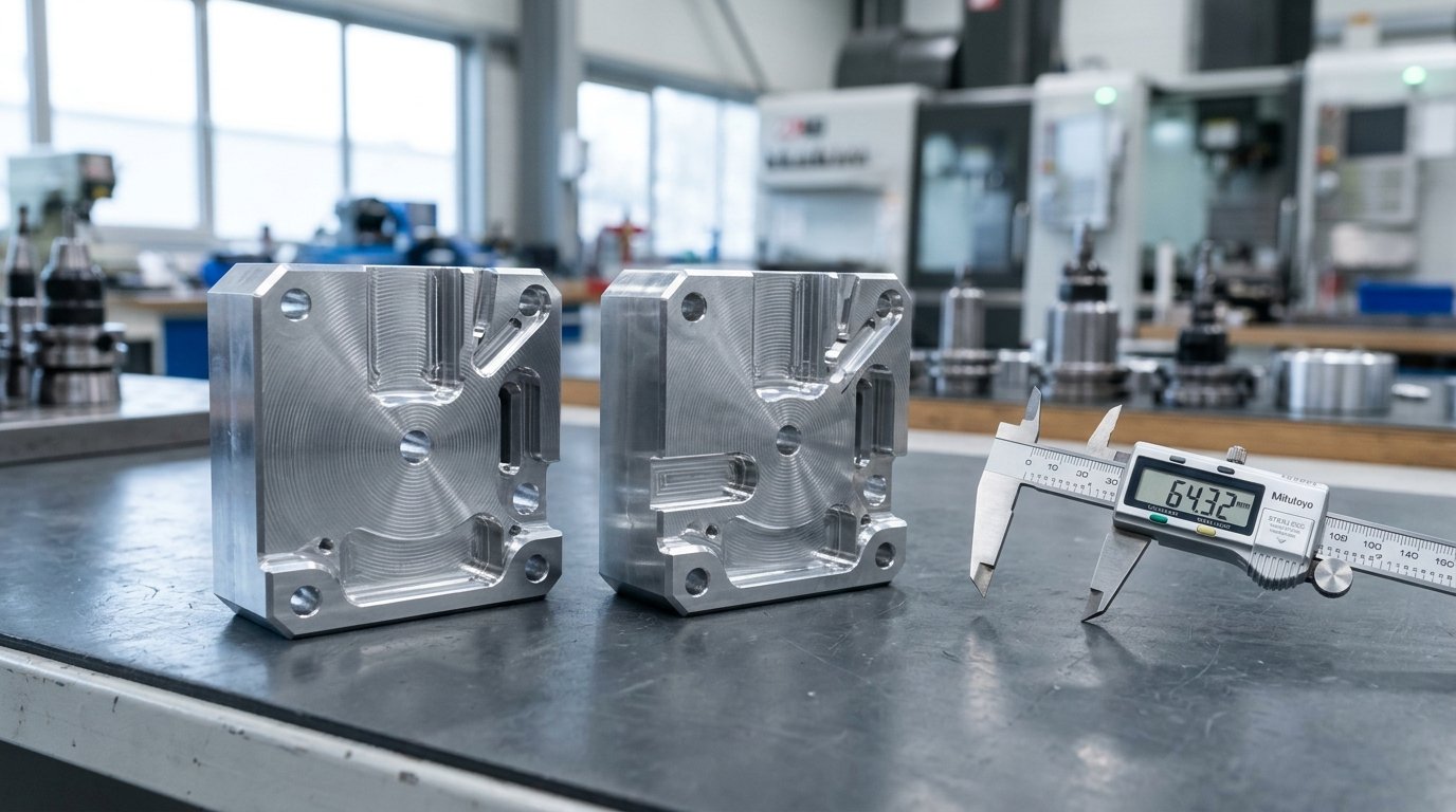
Elite Mold Tech holds ±0.005 in (±0.127 mm) as a standard tolerance on aluminum parts. For critical features, we hold ±0.001 in (±0.025 mm) on request. Holes are typically held to ±0.002 in (±0.05 mm). Flatness is within 0.002 in per 6 in (Elite Mold Tech capability table, 2026).
Aluminum is one of the easiest metals to hold to tight limits. It cuts cleanly, creates little heat compared with harder alloys, and does not work-harden. That is why precision aluminum CNC machining is common in aerospace, robotics, and electronics.
Recurso | Typical limit | Metric |
Standard linear tolerance | ±0.005 in | ±0.127 mm |
Tight tolerance (on request) | ±0.001 in | ±0.025 mm |
Hole diameter | ±0.002 in | ±0,05 mm |
Planicidade | 0.002 in per 6 in | 0.05 mm per 152 mm |
Minimum wall thickness | 0.030 in | 0,75 mm |
As-machined surface roughness | Ra 125 μin | Ra 3.2 μm |
Source: Elite Mold Tech aluminum CNC machining capability table (2026). Metric values for flatness are converted from the inch values.
For the full service scope, see our aluminum CNC machining page.
What is the difference between standard and tight tolerance?
Standard tolerance applies to every dimension that has no specific note on the drawing. Tight tolerance applies only to features you mark. Standard limits keep cost low. Tight limits need slower cuts, extra inspection, and sometimes a second setup, so the price rises with each feature you tighten.
Many drawings fall into three levels:
- General (±0.005 in). Outer shapes, clearance holes, cosmetic surfaces.
- Functional (±0.002 in). Bearing bores, locating pins, press-fit seats.
- Precision (±0.001 in). Sealing faces, optical mounts, mating gauge features.
The trick is to give each feature the level it needs. A drawing that holds ±0.001 in on every face costs far more than one that holds it on two faces.
How do ISO 2768 tolerance classes work?
ISO 2768-1 sets general tolerances for dimensions with no individual tolerance. It defines four classes: fine (f), medium (m), coarse (c), and very coarse (v). When a drawing says “ISO 2768-m,” every unmarked dimension follows the medium table. This saves you from writing a tolerance on every line (ISO 2768-1, 1989).
Nominal size range | Fine (f) | Medium (m) | Coarse (c) |
0.5 to 3 mm | ±0,05 mm | ±0.1 mm | ±0.2 mm |
Over 3 to 6 mm | ±0,05 mm | ±0.1 mm | ±0.3 mm |
Over 6 to 30 mm | ±0.1 mm | ±0.2 mm | ±0.5 mm |
Over 30 to 120 mm | ±0.15 mm | ±0.3 mm | ±0.8 mm |
Source: ISO 2768-1 general tolerances for linear dimensions. Check the current edition of the standard before you cite it on a drawing.
Our standard ±0.005 in (±0.127 mm) is tighter than the medium class on larger sizes. You can read the standard itself at ISO 2768-1. If your drawing names a class, we follow it. If it names none, we use our standard limit.
What is GD&T and why does it matter?
GD&T stands for geometric dimensioning and tolerancing. It controls the form of a feature, not just its size. Flatness, position, perpendicularity, and runout are common callouts. A hole can be the right size but in the wrong place, and only a position callout catches that.
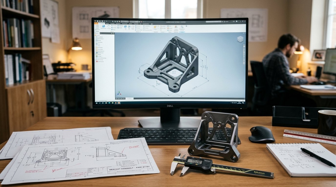
A 2D drawing with GD&T gives the engineer the full intent. It shows which datum the part sits on, which faces mate, and which limits matter. We recommend sending both the 3D file and the 2D drawing with every inquiry. Our garantia de qualidade process checks the marked features against your drawing.
What affects aluminum machining accuracy?
Four things change the accuracy you get: heat, part stress, fixturing, and tool wear. Aluminum expands more than steel as it warms. Cutting forces also bend thin features. A good process controls each one.
- Heat. Aluminum grows about 23 μm per meter for each 1 °C of temperature change. A 100 mm part that warms by 10 °C grows about 0.023 mm. That is nearly the whole ±0.025 mm window.
- Residual stress. Plate cut from a heat-treated block can hold internal stress. Machining a deep pocket releases it and the part bows. A stress-relieved temper such as T651 reduces the effect.
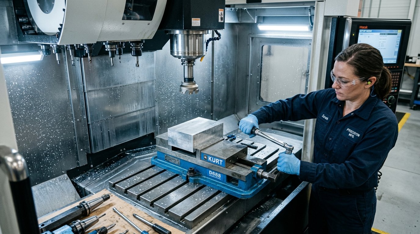
- Fixturing. Clamps that squeeze a thin wall bend it. The part springs back when released and the measurement shifts.
- Tool wear. A worn cutter leaves size drift across a long run. Regular tool checks and in-process probing control it.
The expansion value is a general engineering figure for aluminum. We measure parts in a controlled room so that heat does not distort the result.
How does material choice affect tolerance?
All the aluminum grades we machine hold the same standard tolerance. The grade changes cutting time and tool wear, not the limit we quote. 6061 machines fastest. 7075 is harder and wears tools faster, so a tight 7075 job takes longer.
Nosso guia sobre aluminum alloys for CNC machining compares every grade we stock. For most tight-tolerance work, 6061-T6 or 6082 gives the best balance of stability and cost.
How do finishes change your final dimensions?
Finishes add thickness, so they change size. Type II anodizing adds 5 to 25 μm per surface (Elite Mold Tech, 2026), and the coating grows both into and out of the surface. A hole that measures ±0.025 mm before anodizing loses some of that window after it.
Plan for it in three steps:
- Tell us the finish when you send the drawing.
- State whether the tolerance applies before or after coating.
- Mask critical bores and threads if they must stay exact.
Bead blasting and polishing remove or move a small amount of material as well. See every option on our acabamento da superfície page.
How does 5-axis machining help with tolerance?
5-axis machines reach several faces in one setup. Fewer setups means less re-clamping, and every re-clamp adds a small error. Features cut in one setup stay in true position to each other, which is what position tolerances ask for.
For housings, manifolds, and curved parts, look at our 5-axis CNC machining service. Our capacidade page lists the equipment behind these limits.
How do you set the right tolerance in five steps?
Set tolerances by function, not by habit. These five steps keep the drawing tight where it counts and loose everywhere else.
- List the mating features. Mark every face, hole, or pin that touches another part.
- Pick a general class. Use our ±0.005 in standard or name an ISO 2768 class.
- Tighten only the functional features. Start at ±0.002 in and go to ±0.001 in only where a test needs it.
- Add GD&T for form and position. Use flatness, position, or runout where size alone is not enough.
- State the finish. Say whether limits apply before or after coating.
Following these steps cuts the cost of precision machining without hurting how the part works.
Send your drawing for a tolerance review
Not sure which limits to call out? Upload your 3D file and 2D drawing, and our engineers will review every tolerance and suggest where to loosen or tighten. We guarantee a response within 12 hours, and most orders take under 10 days.
Pronto para começar? Solicite um orçamento or visit the Elite Mold Tech home page to see our other CNC services.
Perguntas frequentes
Q: What is the standard tolerance for aluminum CNC machining?
A: Our standard is ±0.005 in (±0.127 mm). It applies to any dimension with no specific note on the drawing. For critical features, we hold ±0.001 in (±0.025 mm) on request when you send a 2D drawing with GD&T.
Q: Can you hold ±0.001 in on aluminum?
A: Yes, on the features you mark as critical. Tight limits need slower cuts, extra inspection, and often a controlled measuring room. Apply them only to mating faces or bores, because each one adds cost to the part.
Q: Does anodizing change tolerance?
A: Yes. Type II anodizing adds 5 to 25 μm per surface, so holes shrink and shafts grow. Tell us whether your limits apply before or after coating, and we plan the machined size to match your final target.
Q: Which aluminum alloy holds tolerance best?
A: 6061-T6 is the most stable and cheapest choice for tight work, and 6082 is a close second. 7075 holds the same limits but takes longer to cut. A stress-relieved temper such as T651 helps on large flat parts.
Q: What is the minimum wall thickness for aluminum parts?
A: Our minimum is 0.75 mm. Thinner walls flex under the cutter and are hard to hold flat. For long walls, design thicker, and add ribs where you need stiffness without adding bulk.
Q: Do I need a 2D drawing, or is a 3D file enough?
A: Send both. The 3D file gives the shape, and the 2D drawing gives the tolerances, datums, and finish notes. Without the drawing, we quote the standard tolerance and cannot inspect against critical limits.
Sources
- Elite Mold Tech, Aluminum CNC Machining capability table (2026): elitemoldtech.com/aluminum-cnc-machining
- ISO 2768-1, General tolerances for linear and angular dimensions: iso.org