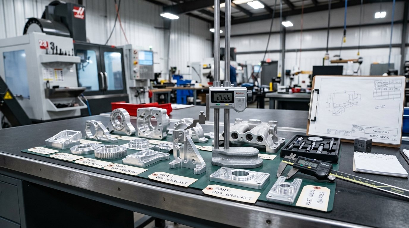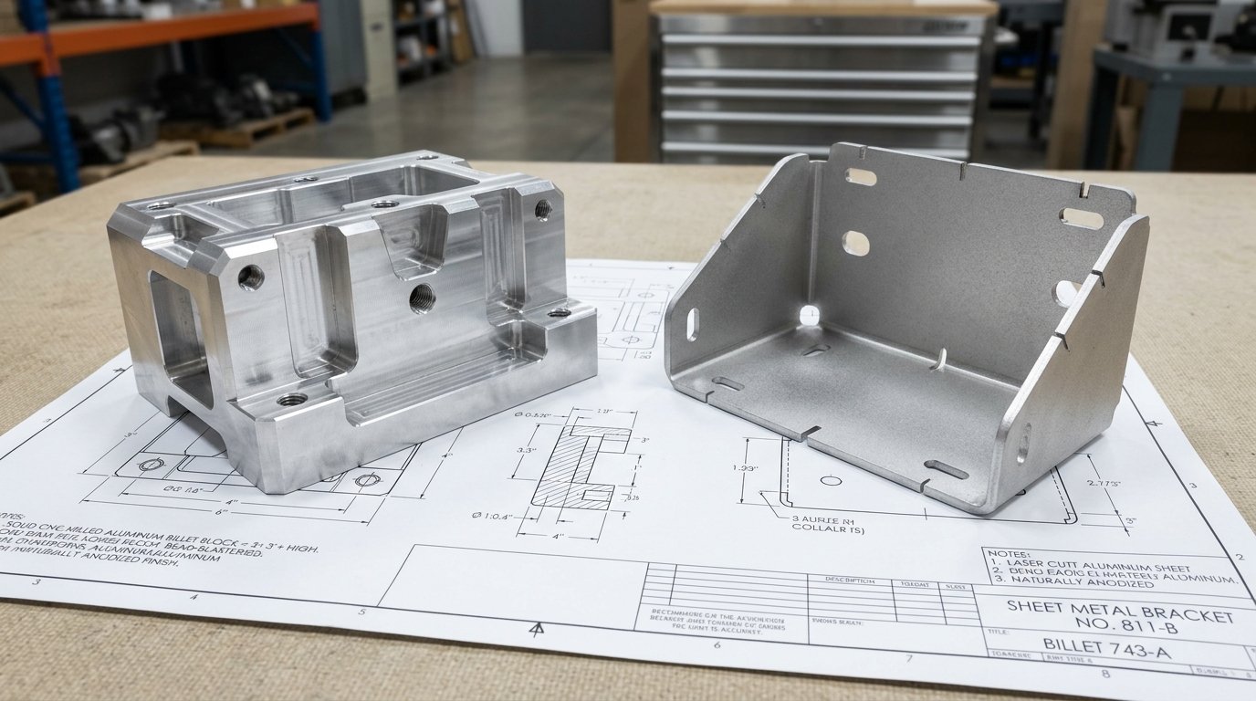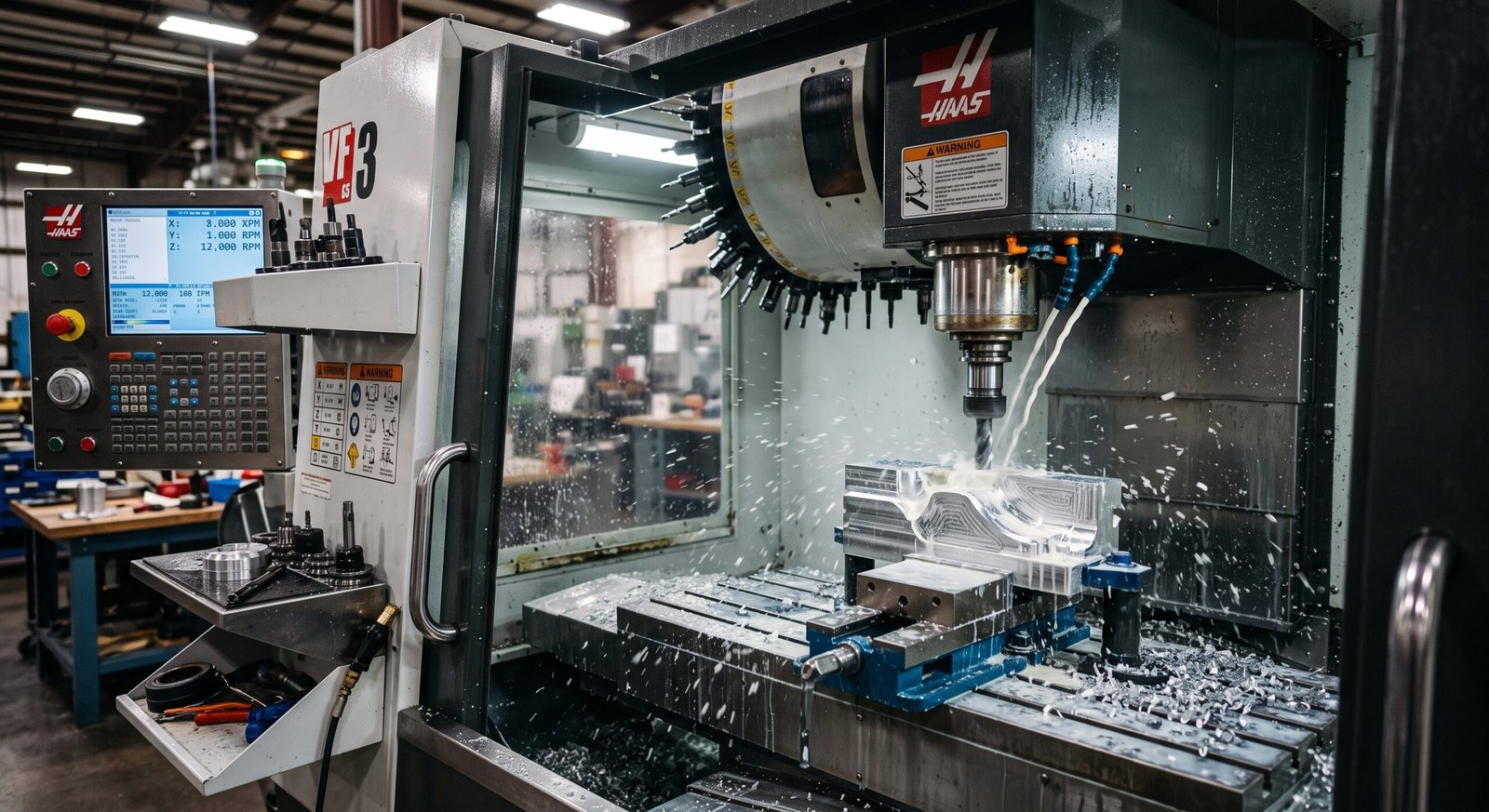
A bearing seat runs 0.02mm oversized. The product ships. Three months later the bearing walks under load and the part fails in the field. A connector housing comes in 0.03mm undersized on the mating bore, and it won’t assemble at all, so it goes straight to scrap. Look at either part and you would see nothing wrong. The whole problem was two hundredths of a millimeter.
Tolerance is the one number on a drawing nobody questions until something breaks. And when an engineer does not really know what a given tolerance costs to produce, it usually ends one of two ways: parts that are over-toleranced and cost double what they should, or parts that are under-toleranced and fail at assembly or out in service. Same fix for both. Know what the number means, know what the standards actually require, and know how going from 0.1mm to 0.005mm bends the cost curve.
That is what this guide walks through. You will see how the ISO 2768 tolerance classes handle every dimension you did not call out, how GD&T controls the geometry a plus-minus number cannot, where bilateral and unilateral tolerances differ, what each tolerance tier does to cost, and a short set of rules for specifying precision that protects function without paying for accuracy the part never needed.
| Réponse rapide: CNC machining tolerances define the allowable dimensional variation from a nominal dimension. Standard CNC practice achieves 0.05mm to 0.1mm (ISO 2768 medium class) on unspecified dimensions without additional cost. Precision features such as bearing seats, sealing surfaces, and close-fit bores are held to 0.01mm to 0.02mm at moderate cost premium. Tight-tolerance work at 0.005mm requires dedicated setups, premium tooling, slower feeds, and CMM inspection on every part, adding 2 to 4 times the cost of standard tolerancing. Only 20 percent of features on a typical part genuinely need tight tolerances. Over-tolerancing the remaining 80 percent is the single most common driver of avoidable CNC machining cost. |
What Is a CNC Machining Tolerance, and Why Does It Exist?
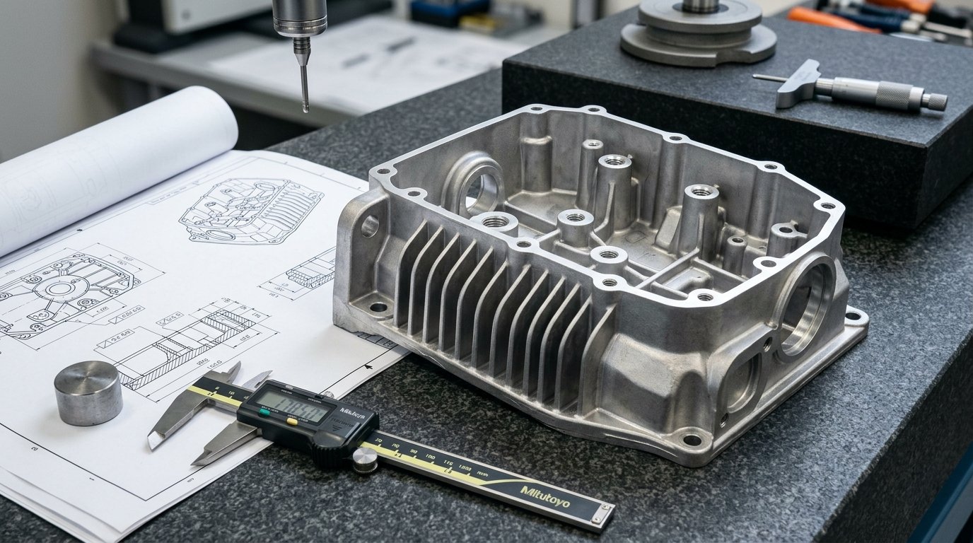
A CNC machining tolerance is the range of dimensional variation a part is allowed to have around its nominal, or target, value and still be accepted. Picture a plus-minus band. Call out 25.000mm with a tolerance of 0.05mm and anything measuring between 24.950mm and 25.050mm passes; step outside that band and it is a reject.
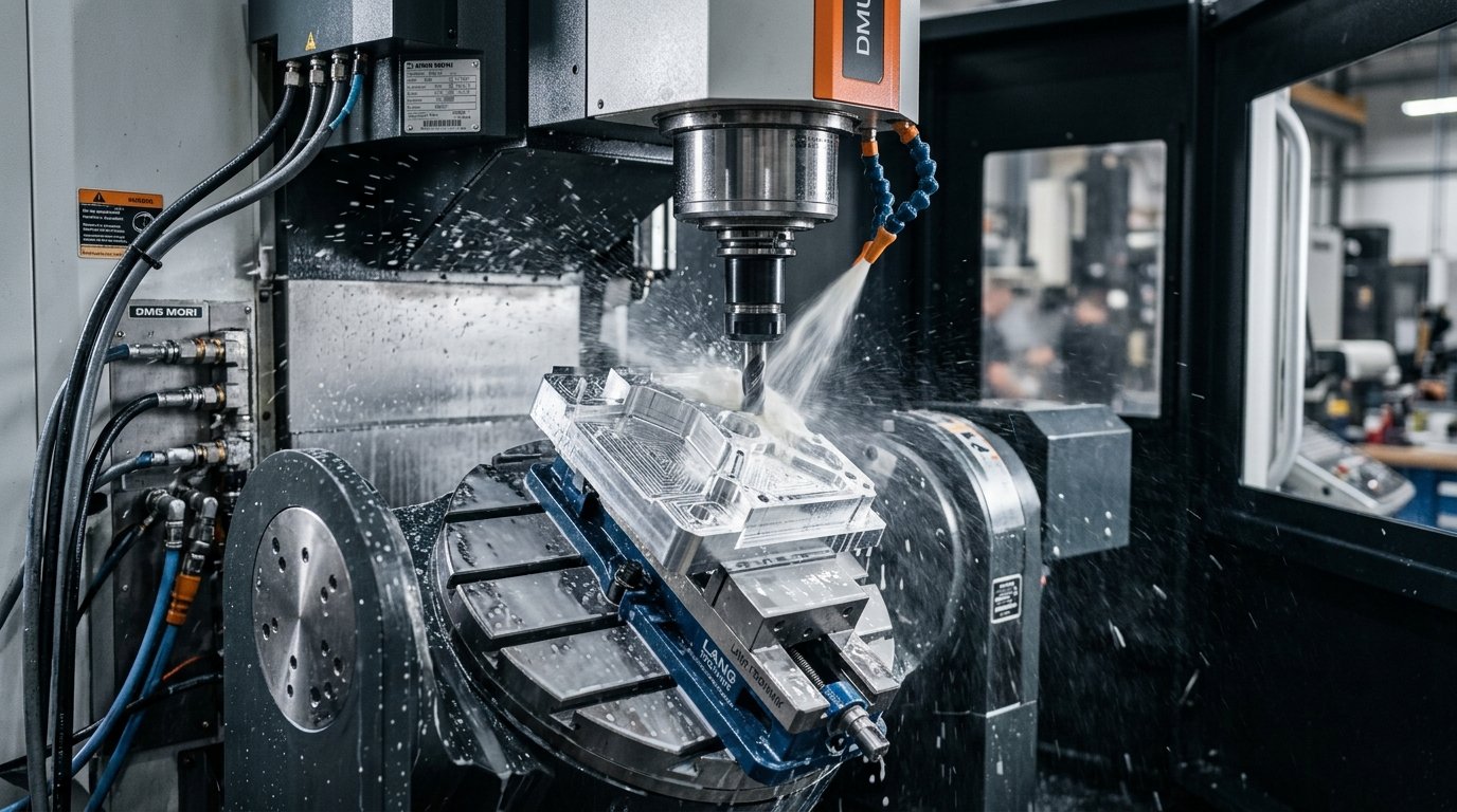
Why have tolerances at all? Because no process cuts the exact same dimension on every part, every cycle. Tool wear, thermal growth in both the workpiece and the machine, small shifts in fixture position, vibration, deflection under cutting force, they all nudge the finished size away from what you programmed. A tolerance is simply your decision about how much of that unavoidable variation you can live with before assembly, function, or reliability starts to suffer.
Here is the part people miss: setting a tolerance is a functional call, not a precision preference. The number should track what actually happens to the product if the dimension drifts. If 0.1mm of variation causes no assembly issue, no leak, and no loss of performance, then 0.1mm is the right tolerance. Tightening that same dimension to 0.01mm buys you nothing and costs real money.
What Does ISO 2768 Specify, and How Does It Govern Your Unspecified Dimensions?
ISO 2768 is the international general-tolerance standard for machined parts, and it does one crucial job: any dimension on your drawing without its own tolerance callout falls back to the class named in the title block. In practice that means ISO 2768 quietly governs most of the dimensions on a typical part, because usually only the critical mating and functional features get individual callouts.
Part 1 of the standard handles linear and angular dimensions, sorted into four classes by letter: f (fine), m (medium), c (coarse), and v (very coarse). The allowed band grows with the size of the feature, which makes sense. Holding a 200mm feature to the same absolute tolerance as a 5mm feature would take far more precision for no good reason.
| Nominal Dimension Range | Class f (Fine) | Class m (Medium) | Class c (Coarse) | Class v (Very Coarse) |
|---|---|---|---|---|
| 0.5mm to 3mm | 0.05mm | 0.1mm | 0.2mm | 0.5mm |
| 3mm to 30mm | 0.05mm | 0.2mm | 0.5mm | 1.0mm |
| 30mm to 120mm | 0.1mm | 0.3mm | 0.8mm | 1.5mm |
| 120mm to 400mm | 0.15mm | 0.5mm | 1.2mm | 2.5mm |
| 400mm to 1000mm | 0.2mm | 0.8mm | 2.0mm | 4.0mm |
| 1000mm to 2000mm | 0.3mm | 1.2mm | 3.0mm | 6.0mm |
ISO 2768-m, the medium class, is the workhorse of commercial CNC machining. Standard 3-axis equipment hits it without special setups, and it is the baseline you get whenever no explicit tolerance standard shows up on the order or in the title block [1]. The fine class, ISO 2768-f, asks for more careful machining and suits precision assemblies. Classes c and v show up on sheet metal, castings, and non-functional features where loose control is perfectly fine.
What Is the Difference Between Bilateral and Unilateral Tolerances?
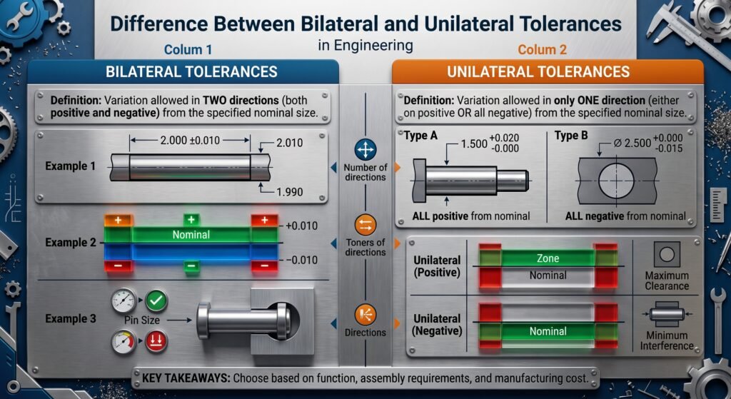
Bilateral and unilateral tolerances are just two ways of describing where the allowed variation sits relative to nominal. Getting the distinction right is what lets you control the real functional requirement of a feature instead of guessing at it.
Bilateral Tolerances
A bilateral tolerance permits variation in both directions off nominal, and it is the default for most machined features. Specify a 20.000mm shaft at plus-minus 0.05mm and anything from 19.950mm to 20.050mm is good; the part can come in a touch over or a touch under and still pass. Whenever the requirement is simply to land inside a band centered on nominal, bilateral is the right tool.
Unilateral Tolerances
A unilateral tolerance only allows drift in one direction. Call out a shaft as 20.000mm, plus 0.000 minus 0.050mm, and it can sit at nominal or below, never above. That is exactly what you want when the functional limit runs one way, the classic shaft-to-bore fit, where an oversized shaft kills assembly outright but an undersized one just opens up the clearance a little. Use bilateral where the function really needs unilateral and you will ship parts that pass inspection and then refuse to go together.
Tolerance Stack-Up
Tolerance stack-up is what you get when several individual tolerances pile onto one final assembly dimension. Stack three parts in a line, each held to 0.1mm, and worst case the assembly can drift 0.3mm once all three tolerances happen to add in the same direction. In assemblies with a lot of mating parts, a stack-up analysis is how you find out whether the tolerances on each part are actually tight enough to guarantee the assembly works across a full production run. And here is the trade: tightening each feature is the priciest way to fix a stack-up. Redesigning to stack fewer dimensions in the first place is almost always the cheaper one.
What Does GD&T Control That Plus-Minus Tolerances Cannot?
Plus-minus tolerances control size, whether a feature falls inside its band of allowable size. GD&T, or Geometric Dimensioning and Tolerancing (ASME Y14.5 in North America, ISO 1101 internationally), controls the relationship between features: their form, orientation, location, and runout. Those are things a size tolerance simply cannot describe.
Key GD&T Controls Relevant to CNC Machining
- Flatness controls how flat a surface is, no matter where it sits in space. A 0.02mm flatness callout means the whole surface has to fit between two parallel planes 0.02mm apart. You will see it on sealing surfaces, mounting faces, and precision reference datums.
- Perpendicularity controls how close a surface or axis holds to 90 degrees against a datum. It matters for bores that have to take a perpendicular shaft without binding, and for mating faces that need to seat flat under clamping load.
- True position controls where a feature sits, usually a hole or boss, relative to a datum reference frame. It replaces the separate X and Y plus-minus callouts you would otherwise need for hole location, and it describes a round tolerance zone instead of a square one. That round zone is 57 percent larger, so it allows more real manufacturing variation while still guaranteeing the part goes together.
- Runout controls how far a surface wanders from true circularity and concentricity as it spins about a datum axis. It belongs on rotating components, bearing journals, and sealing surfaces that have to stay in contact through rotation.
- Cylindricity controls the whole form of a cylindrical feature at once, keeping it round, straight, and correctly tapered down its length. It is critical on precision bearing bores and hydraulic cylinder bores, where the seal rides the full length of the cylindrical contact.
GD&T controls sit on top of size tolerances, not in place of them. A bore can carry both a diameter tolerance and a perpendicularity callout to a datum face. Specify the GD&T well and you strip ambiguity out of machining and inspection, which cuts the odds of a part that measures fine on size but still fails at assembly because of a geometric error the size tolerance never saw.
How Does Tightening Tolerance Affect CNC Machining Cost?
Tolerance and cost do not move in a straight line, they move exponentially. Going from ISO 2768-m (roughly 0.1mm to 0.3mm depending on feature size) down to 0.05mm nudges cost up a little; you slow the feeds and watch tool condition more closely. Drop from 0.05mm to 0.01mm and now you are into dedicated precision setups, temperature-stabilized machining on some features, premium tooling, and in-process gauging. Push below 0.005mm and you are usually past standard milling and turning altogether, into grinding or lapping, with 100 percent CMM inspection on the critical features.
| Tolerance Tier | Gamme typique | Achievable By | Cost Multiplier vs Standard | Inspection Method | Applications typiques |
|---|---|---|---|---|---|
| Standard | 0.1mm to 0.5mm | 3-axis CNC standard setup | 1,0x (référence) | Caliper or CMM sampling | Enclosures, brackets, non-mating features |
| Précision | 0.02mm to 0.1mm | 3-axis CNC with care or 5-axis | 1.3x to 2.0x | CMM on critical features | Assembly fits, housing bores, locating features |
| Tight | 0.005mm to 0.02mm | Precision CNC, slow feeds, premium tooling | 2.0x to 4.0x | 100% CMM on tight features | Bearing seats, sealing grooves, precision shafts |
| Ultra-tight | Below 0.005mm | Grinding, lapping, honing post-CNC | 4.0x to 24x | 100% CMM with traceable calibration | Gauge blocks, precision spindles, master references |
That curve lines up with published work from Tormach and Ohio University: tightening from 0.030 inch (0.76mm) to 0.001 inch (0.025mm) runs machining cost up about 4 times, and chasing 0.0001 inch (0.0025mm) pushes it roughly 24 times over standard practice [2]. The takeaway is blunt. Spend tight tolerances only where the part genuinely fails if the dimension leaves the band. On most parts that is 10 to 20 percent of the dimensions; the other 80 to 90 percent can ride on ISO 2768-m or a modest precision callout.
How Do You Specify Tolerances That Protect Function Without Overpaying?
Specifying a tolerance is a design decision that lands straight on your manufacturing cost. The five rules below are the guidance we lean on, drawn from precision engineering practice and from the DFM reviews Elite Mold Tech runs across thousands of new part programs.
- Rule 1: Put ISO 2768-m in the title block. It sets a sensible default for every unspecified dimension and tells the machinist what baseline precision to expect, without you sprinkling callouts across every feature.
- Rule 2: Add a tight callout only where the part actually fails outside the standard band. Ask it plainly. If this dimension lands 0.2mm off nominal, does the part refuse to assemble, leak, or break under load? If not, ISO 2768-m has you covered.
- Rule 3: Reach for GD&T on the relationships between features, not just their size. A hole located with only X and Y plus-minus callouts creates a square tolerance zone that passes parts in the corners that will not really assemble. True position gives you the correct round zone and hands back 57 percent more manufacturing room while still guaranteeing fit.
- Rule 4: Run a stack-up analysis on assemblies before you lock in individual feature tolerances. Tightening one feature by 50 percent to rescue a stack-up problem often costs more than redesigning the assembly to stack fewer dimensions.
- Rule 5: Get a DFM review from Elite Mold Tech before the drawing goes out. The thing we flag most often is tight tolerances stuck on non-functional features out of habit or caution. Loosening three or four of those per part routinely trims 20 to 40 percent off machining cost with zero effect on how the part works.
| Not Sure Which Tolerances Your Part Actually Needs? Upload your STEP or IGES file and 2D drawing to Elite Mold Tech and receive a free DFM review within 12 hours. Our engineering team reviews every tolerance callout against the functional requirement of each feature, identifies over-toleranced dimensions, and provides a revised tolerance recommendation that reduces your per-part cost without affecting assembly or performance. All uploads are secure and covered by NDA on request.Visit elitemoldtech.com to upload your drawings and start the tolerance review. |
Guides et ressources connexes d'Elite Mold Tech
Guides connexes : Guide complet de sélection des processus de fabrication, 5-axis vs 3-axis CNC machining, Services d'usinage CNC.
Références faisant autorité : Norme ISO 2768-1 relative aux tolérances générales, ASME Y14.5 GD&T standards.
Demandez une analyse DFM à Elite Mold Tech
Prêt à passer du dessin à la pièce ? Envoyez votre fichier CAO à Elite Mold Tech et recevez une analyse DFM dans les 12 heures, accompagnée des commentaires de notre équipe d'ingénieurs concernant les tolérances, les matériaux et les coûts, avant de vous engager dans la fabrication des outils.
Questions fréquemment posées
What is the tightest tolerance CNC machining can hold in normal production?
In stable aluminum and steel, standard 3-axis milling and turning holds 0.05mm on prismatic features comfortably, with normal tooling and setup. Add dedicated precision setups, premium tooling, a temperature-controlled environment, and in-process gauging, and a modern machining center will hit 0.005mm on specific critical features in production. That is about the practical floor for standard CNC without a finishing operation afterward. Need tighter than 0.005mm, think precision bearing bores, gauge surfaces, high-precision spindle journals, and you are usually grinding, honing, or lapping after the CNC work to reach final size. 5-axis CNC machining service reaches 0.005mm on complex multi-face parts by cutting them in one setup instead of accumulating error across repositioning. At Elite Mold Tech we hold 0.005mm on critical features in aluminum, stainless, and titanium Grade 5 as regular production.
Why do tight tolerances increase CNC machining cost so dramatically?
Tight tolerances drive cost up through five things that stack on each other. Feeds slow down first: lighter cuts at lower feed rates mean more machine time per part. Then the passes multiply, as rough, semi-finish, and finish replace the single pass standard work gets away with. Tooling goes premium too, sharper tools with tighter runout, swapped out more often and costing more each. Inspection climbs, because every tight feature has to be measured and logged, piling CMM and operator time onto each part. And scrap rises, since more parts miss the band, and that scrap gets spread across every good part in the quote. Work from Ohio State University and Tormach backs this up: going from standard to 0.001 inch (0.025mm) roughly quadruples cost, and 0.0001 inch (0.0025mm) runs it up about 24 times.
What is ISO 2768-m and when should I specify it?
ISO 2768-m is the medium tolerance class in the ISO 2768 general-machining standard. Drop it in the title block and it becomes the default for every dimension that does not carry its own callout. For a feature between 30mm and 120mm, that default is 0.3mm; between 3mm and 30mm, it is 0.2mm. Standard 3-axis equipment holds it with no special setups, and it is the baseline precision behind most commercial CNC work. Use it as your title-block standard on any drawing that does not have a real reason for tighter general tolerances. It keeps the drawing clean, tells the machinist exactly what baseline to expect, and gives you plenty of precision for the structural and housing features that make up most commercial and industrial parts.
What is tolerance stack-up and how does it affect part design?
Tolerance stack-up is the total dimensional variation you get from combining the tolerances of several parts in an assembly. Bolt components together in sequence and the real dimension at any critical interface is the algebraic sum of every contributing part’s variation. Worst case, all those tolerances add the same direction at once. Take an assembly with five contributing dimensions, each at 0.1mm, and the worst-case stack at the final interface is 0.5mm. So if that gap has to stay within 0.2mm to work, the stack fails even though every part passed its own inspection. Your options: tighten the individual features (expensive), redesign to cut the number of dimensions feeding the stack (the one we would pick), or use statistical methods to predict the likely spread and accept that a small share of assemblies will land outside target. Elite Mold Tech’s DFM review covers stack-up on critical interfaces when you ask for it.
How is CNC machining tolerance different from surface finish (Ra)?
Tolerance and surface finish describe two different things about the same feature, and they are specified independently. Tolerance, in millimeters or inches plus-minus, is about size and location: how big, how far, how straight, how flat a feature is allowed to be. Surface finish, given as Ra (the arithmetic mean roughness in micrometers), is about texture, the microscopic peaks and valleys the cutting process leaves behind. A feature can sit dead-on dimensionally and still have a surface rough enough to wear early or seal poorly. Flip it around and a part can wear a beautiful Ra 0.4 micrometer mirror finish and still be a reject because its size is out of band. Both get specified, both get inspected, separately. Standard milling lands around Ra 0.8 to 3.2 micrometers. Precision finish passes, ball-nosed tools on aluminum, and tuned feed rates bring that to Ra 0.4 to 0.8. Grinding and lapping reach Ra 0.1 or better for the most demanding sealing and bearing surfaces.
What is the difference between ISO 2768 and GD&T, and do I need both?
They do different jobs, and most precision drawings use both together. ISO 2768 is a dimensional standard: it sets how much a size can vary, whether length, diameter, depth, or angle. It answers how big or small. GD&T (ASME Y14.5 here, ISO 1101 internationally) sets how much the geometry between features can vary: how flat, how perpendicular, how round, how precisely located against a datum reference frame. It answers what shape, and where. Most commercial drawings default all unspecified linear dimensions to ISO 2768-m in the title block, then hang GD&T feature control frames on the features where form or position actually matters. Bearing bores get cylindricity. Mounting faces get flatness and perpendicularity. Hole patterns get true position. Non-functional walls and pockets just ride ISO 2768-m. Used together they are more complete, less ambiguous, and cheaper than leaning on either one alone.
About the Author:
Alex Morgan specializes in technical content for precision manufacturing, with a focus on CNC machining, injection molding, die casting, 3D printing, sheet metal fabrication, and custom mold manufacturing. With more than a decade of experience in B2B manufacturing content and SEO, he creates technically accurate content designed for engineers, product developers, procurement teams, and manufacturing decision-makers. His work helps global manufacturers clearly communicate complex production capabilities, material options, tolerances, tooling processes, and quality standards to customers across the US, Europe, and Asia-Pacific. He writes for manufacturing companies where technical expertise, precision, and reliability matter.